SIF422 24VDC ELESTA, SIF422 24VDC Datasheet
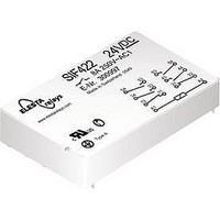
SIF422 24VDC
Manufacturer Part Number
SIF422 24VDC
Description
30M9892
Manufacturer
ELESTA
Datasheet
1.SIF422_12VDC.pdf
(1 pages)
Specifications of SIF422 24VDC
Coil Voltage Vdc Nom
24V
Coil Resistance
870ohm
Contact Current Max
8A
Contact Voltage Ac Nom
250V
Contact Voltage Dc Nom
440V
Contact Configuration
6PST-4NO / 2NC
No. Of Poles
6
Rohs Compliant
Yes
- PCB relay with forcibly guided contacts
- Protective separation between coil and
- EN 50205 type A
- Double and reinforced insulation
- SMD arrangement below relay possible
- Contact mounting:
- Compact height: only 10.9mm
- Mean coil power 0.66W (holding power
Contact material
Type of contact single contact with notched crown
Rated switching capacity 250VAC 8A AC1 2‘000VA
Electr. life AC1 (360 S/h)
Inrush current max.
Switching voltage range
Switching current range*
Switching capacity range* 60mW to 2‘000W (VA)
Contact resistance (as delivered))
* Guide values
Standard coils for direct current (examples)
other voltages on request
Ordering example
SIF 4 2 2 24VDC
Relay data
3,1
3,1
contacts (> 5.5 mm) and contacts side by
side (> 5.5 mm)
0.20W)
4,1
110
12
20
24
48
60
5
15,8
1101 Lafayette Street, Elkhart, IN 46516, Tel: (574) 295-6330, Fax: (574) 293-8013,
< 14.0 > 2.0
< 16.8 > 2.4
< 33.6 > 4.8
< 42.0 > 6.0
< 77 .0 > 11.0
< 3.5
< 8.4
1
53,6
47,4
15,8
> 0.5
> 1.2
15,8
Number of NO contacts
Number of NC contacts
SIF422 4NO/2NC
3,1
133.3
55.8
33.3
13.8
27 .5
11.1
4,1
AgCuNi + 0.2 µm Au
6.0
3,1
5 bis 440VDC/VAC
Type designation
approx.100‘000
1,6
18‘300
3‘460
5‘400
30A for 20ms
Soldering tags
37 .5
215
600
870
Coil voltage
5mA to 8A
< 100mΩ
33,5
30,4
0,3
± 10
± 10
± 10
± 10
± 10
± 13
± 15
[mm]
1,5
American Electronic Components, Inc.
SIF 6 Contacts
Circuit diagram (view on relay upper side)
Tests, regulations
Approvals (in preparation) SEV, UL, cUL, TÜV
Insulation class
Protection class II
Fire protection requirements
General data
Mechanical life
Switching frequency, mechanical
Response time
Drop-out time**
Bounce time of NO contact
Bounce time of NC contact
Shock resistance
Vibration resistance
10-200Hz
Test voltage
coil to contacts
Test voltage
contacts against each other
Test voltage contact open
Insulation resistance at Up 500V
Creeping resistance
Weight
Mounting position
Ambient temperature
Type of protection
Solder bath temperature
Thermal resistance
Temperature limit for coil
Pollution degree
Overvoltage category
Resistance to
short circuiting
** without spark suppression
Insulation terms
Double or reinforced insulation >5.5mm
between all current circuits
Double or reinforced insulation
54
34
A1
12
VDE 0110 / group C 250VAC
53
33
11
SIF-422
1‘000A SCPD 10A AK
63
43
> 10 x 10
21
gL/gG (pre-fuse)
4‘000V
4’000V
NO contact 10g
NO contact 10g
1’500V
-40°C to +70°C
typically 20ms
NC contact 6g
NC contact 2g
typically 12ms
typically 8ms
typically 3ms
64
44
A2
22
6
approx. 35g
RT III (IP67)
UL 94 / V0
operations
VDE 0106
270°C/5s
eff
eff
eff
CTI 175
47K/W
6A RK
120°C
10
15Hz
1min
1min
1min
any
8
III
Ω
3
Kontaktlebensdauer
Diagrammes
U
U
Contact lifetime
1000000
Load limit curve with direct current
Lastgrenzkurve bei Gleichstrom
Erregerspannungsbereich
Excitation voltage range
1) Max. excitation voltage with contact load < 6A
2) Min. excitation voltage (guaranteed values)
No heat accumulation due to intrinsic heating
of other components.
Continuous duty 100%..
Max. switching characteristics
(DIN EN 60947-4-1/ EN 60947-5-1):
AC 1:
AC 15: 230V/6A
DC 1:
DC 13: 24V/5A/0.1Hz
Maximal contact load at AC 1 with 230V:
2 contacts each with 8A
3 contacts each with 6A
4 contacts each with 4.5A
B
N
10000
1000
without previous operation
200
100
500
300
100
70
50
30
20
10
0
2.5
2.0
1.5
1.0
0.5
0
0.1
Current (A)
Switching current (A)
0.1
0
Ambient temperature °C
250V/8A
24V/8A
sales@aecsensors.com
0.2 0.3 0.5 0.7 1.0
DC13
20
AC15
0.5
40
AC1
1
10 W
20 W
100 W
40 W
300 W
250 W
200 W
150 W
60 W
80 W
60
2
1
DC1
2
2
3 4 5 6 7 8 10
3 4 5 6 7 8 910
80
100
Related parts for SIF422 24VDC
Image
Part Number
Description
Manufacturer
Datasheet
Request
R

Part Number:
Description:
30M9891
Manufacturer:
ELESTA
Datasheet:


Part Number:
Description:
ELESTA RELAY 24 VDC, 10 AMP. 250 VAC
Manufacturer:
AMERICAN ELECTRONIC COMPONENTS


Part Number:
Description:
30M9908
Manufacturer:
ELESTA
Datasheet:


Part Number:
Description:
30M9910
Manufacturer:
ELESTA
Datasheet:

Part Number:
Description:
30M9885
Manufacturer:
ELESTA
Datasheet:
Part Number:
Description:
30M9886
Manufacturer:
ELESTA
Datasheet:

Part Number:
Description:
30M9893
Manufacturer:
ELESTA
Datasheet:

Part Number:
Description:
30M9895
Manufacturer:
ELESTA
Datasheet:
Part Number:
Description:
30M9896
Manufacturer:
ELESTA
Datasheet:
Part Number:
Description:
30M9898
Manufacturer:
ELESTA
Datasheet:

Part Number:
Description:
30M9899
Manufacturer:
ELESTA
Datasheet: