1996771-1 TE Connectivity, 1996771-1 Datasheet
1996771-1
Manufacturer Part Number
1996771-1
Description
CONN PIN CONTACT GOLD
Manufacturer
TE Connectivity
Series
-r
Type
Coaxialr
Specifications of 1996771-1
Pin Or Socket
Pin, Center
Contact Termination
Solder
Wire Gauge
Coaxial Cable, 0.047"
Contact Finish
Gold
Contact Finish Thickness
-
Current Rating
-
Product Type
Connector - RF
Rf Connector Type
SMPM
Mount
Floating Panel
Cable Type
.047 Semi-Rigid
Termination Type
Solder
Dielectric Material
Fluoropolymer
Impedance (?)
50
Mount Type
Cable Mount
Plating Material
Gold over Nickel
Contact Base Material
Beryllium Copper
Contact Plating, Mating Area, Material
Gold over Nickel
Center Contact Material
Beryllium Copper
Center Contact Plating
Gold over Nickel
Housing Material
Beryllium Copper
Vita 67
Yes
Rohs/elv Compliance
RoHS compliant, ELV compliant
Lead Free Solder Processes
Hand solderable with tin/lead solder
Rohs/elv Compliance History
Always was RoHS compliant
Lead Free Status / Rohs Status
Lead free / RoHS Compliant
Other names
A103871


1. INTRODUCTION
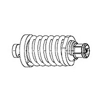
SMPM Floating Panel Mount Cable Jacks (Direct
Solder Attachment) shown in Figure 1 are designed to
be soldered to semi--rigid, conformable, or flexible
coaxial cable with a diameter of 2.16 mm [.085 in.] or
1.19 mm [.047 in.]
The cable jacks are designed to be inserted into a
mounting hole (such as the one in VITA 67, daughter
card module 1996705--3).
2. DESCRIPTION
The cable jacks consists of a body, compression
spring, retaining washer, and center contact. The
compression spring and retaining washer are used to
secure the part into the module. See Figure 1.
3. ASSEMBLY PROCEDURE
E2010 Tyco Electronics Corporation, Berwyn, PA
All Rights Reserved
TE logo and Tyco Electronics are trademarks.
*Trademark. Other products names, logos, or company names might be trademarks of their respective owners.
CAUTION
NOTE
1. Strip the cable to the dimensions shown in
Figure 2.
2. For flexible cable, tin the cable braid.
3. Shape the blunt end of the center conductor to a
cone between 85 and 90. See Figure 3.
4. Insert the cable center conductor into the center
contact inside the rear shell of the cable plug until
the cable bottoms. No braid strands should be
exposed. See Figure 4.
5. Holding the cable center conductor in place and
using 60/40 solder, attach the rear shell to the
cable as shown in Figure 4.
Washer
i
!
Dimensions in this instruction sheet are in
millimeters [with inches in brackets]. Figures and
illustrations are for reference only and are not
drawn to scale.
DO NOT nick the center conductor of the cable.
Take care not to cut the cable braid.
Figure 1
Compression Spring
TOOLING ASSISTANCE CENTER 1- - 800- - 722- - 1111
PRODUCT INFORMATION 1- - 800- - 522- - 6752
Cable Jack
SMPM Floating Panel Mount, Cable Jacks
(Direct Solder Attachment)
1996390- 1, 1996771- 1
4. INSERTING CONNECTOR INTO MODULE
DANGER
1. Insert soldered cable connector into module
mounting hole from the flange side of the module
bottoming the connector body flange on the
module. See Figure 5.
80+10_ Typ
2.03 [.080]
5.33 [.210]
2.03 [.080]
0.25 [.010] Max Typ
Flat (Radius Optional)
Semi- - Rigid and Conformable Cables
To avoid personal injury, make sure to follow all
local practices and safety precautions when
working with soldering equipment.
This controlled document is subject to change.
For latest revision and Regional Customer Service,
visit our website at www.tycoelectronics.com
85- - 90_
Stripping Dimensions
Flexible Cable
Center
Conductor
Figure 2
Figure 3
Figure 4
Center
Conductor
Braid
Cable Center
Conductor
408- - 10373
Instruction Sheet
Outer
Conductor
06 AUG 10 Rev B
Jacket
Solder Here
Cable
1 of 2
LOC B
Related parts for 1996771-1
Image
Part Number
Description
Manufacturer
Datasheet
Request
R

Part Number:
Description:
Printers THERMAL PRINTER HS-SLEEVE MARKER
Manufacturer:
TE Connectivity


Part Number:
Description:
High Speed / Modular Connectors 30P HEADER ASSY
Manufacturer:
TE Connectivity
Datasheet:

Part Number:
Description:
High Speed / Modular Connectors REC 6X005P R/A LT B-PLANE HS3
Manufacturer:
TE Connectivity
Datasheet:

Part Number:
Description:
High Speed / Modular Connectors 2MM HM RCPT 50P R/A AU
Manufacturer:
TE Connectivity
Datasheet:

Part Number:
Description:
High Speed / Modular Connectors 2MM HM RCPT 50P R/A AU
Manufacturer:
TE Connectivity
Datasheet:


Part Number:
Description:
Manufacturer:
TE Connectivity
Datasheet:


Part Number:
Description:
Manufacturer:
TE Connectivity
Datasheet:

Part Number:
Description:
Manufacturer:
TE Connectivity
Datasheet:

Part Number:
Description:
Manufacturer:
TE Connectivity
Datasheet:
1996771-1 Summary of contents
Page 1
... TE logo and Tyco Electronics are trademarks. *Trademark. Other products names, logos, or company names might be trademarks of their respective owners. SMPM Floating Panel Mount, Cable Jacks (Direct Solder Attachment) 1996390- 1, 1996771- 1 Cable Jack Semi- - Rigid and Conformable Cables 0.25 [.010] Max Typ Flat (Radius Optional) 2 ...
Page 2
Insert compression spring in module mounting hole and over connector body from the module mating face. 3. Place retaining washer into insertion tool 2101595--1 aligning the flats on the tool with the external flats on the washer. 4. Align ...