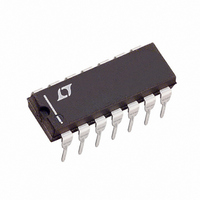
LT1684CN#PBF Linear Technology, LT1684CN#PBF Datasheet - Page 3

LT1684CN#PBF
Manufacturer Part Number
LT1684CN#PBF
Description
IC RING TONE GENERATOR 14-DIP
Manufacturer
Linear Technology
Datasheet
1.LT1684CN.pdf
(16 pages)
Specifications of LT1684CN#PBF
Function
Tone Generator
Number Of Circuits
1
Operating Temperature
0°C ~ 125°C
Mounting Type
Through Hole
Package / Case
14-DIP (0.300", 7.62mm)
Lead Free Status / RoHS Status
Lead free / RoHS Compliant
Current - Supply
-
Voltage - Supply
-
Power (watts)
-
Interface
-
Available stocks
Company
Part Number
Manufacturer
Quantity
Price
ELECTRICAL CHARACTERISTICS
SYMBOL
Supply and Protection
I
|V
|V
V
V
PWM Receiver
f
V
R
R
BG Buffer
V
V
I
R
t
t
t
t
Output Amplifier
V
R
I
Note 1: Absolute Maximum Ratings are those values beyond which the life
of the device may be impaired.
Note 2: IC Supply current specification represents unloaded condition and
does not include external FET gate pull up/down currents (GATE
pins). Actual total IC bias currents will be higher and vary with operating
conditions. See Applications Information.
The
V
S
PWM
BGOUTSC
r
f
pr
pf
OUTSC
GATE
GATE
IN
BGOUT
BGOUTOS
OUTOS
IN
INA,INB
BGOUT
t
t
OUT
+
r-f
p
+
–
|
|
– V
+
–
denotes the specifications which apply over the full operating temperature range, otherwise specifications are at T
–
= 20V, Voltages referenced to pin OUT, V
PARAMETER
DC Supply Current (Note 2)
Local Supply Voltages
Active Tracking Supply FET
Bias Voltage
Active Tracking Supply FET
Bias Voltage
Input Carrier Frequency
Minimum Valid Differential Input
Differential Input Threshold
| IN A – IN B |
Differential Input Overdrive Impedance
(Note 3, 5)
Single-Ended Input Impedance
(Note 5)
BG
Output Offset Voltage
[(V
BG
BG
BG
BG
BG
BG
Transition to 10% Output (Rising Edge)
BG
Transition to 90% Output (Falling Edge)
BG
Rising Edge – Falling Edge
OUT Offset Voltage
OUT Output Impedance
OUT Short-Circuit Current
OUT
OUT
OUT
OUT
OUT
OUT
OUT
OUT
OUT
BGOUT
Normalized Voltage
Short-Circuit Current
Output Impedance
Rise Time (10% to 90%)
Fall Time (10% to 90%)
RiseTime – Fall Time
Propagation Delay PWM Input
Propagation Delay PWM Input
Propagation Delay
+) + (V
BGOUT
–)]/2
OUT
CONDITIONS
IN A – IN B 1.6V
V
V
I
AT
I
AT
IN A – IN B or IN B – IN A
V
To Pin OUT
Magnitude |V
– 2mA I
R
R
R
R
V
R
–10mA I
10mA I
LIM
LIM
GATE
GATE
GATE
GATE
IN
AMPIN
OUT
OUT
OUT
OUT
AMPIN
REF
REF
> V
+
–
= V
+ = –100 A,
– = 100 A,
+
–
= 5k, C
= 5k, C
= 5k, C
= 5k, C
Shorted to OUT
Shorted to V
= 0V
= 0V
TH
+
= 0v, I
= 10k (Note 4)
, GATE
ATREF
OUT
BGOUT
+ 100mV
V
V
LIM
+
–
OUT
OUT
OUT
OUT
BGOUT
+ –100mA, LIM
OUT
unless otherwise noted.
–
100mA, LIM
= 10pF
= 10pF
= 10pF
= 10pF
2mA
= 0A
–
|
Note 3: PWM inputs are high impedance through 100mV beyond the
input thresholds.
Note 4: 10k resistor from pin AMPIN to ground.
Note 5: Guaranteed but not tested.
–
Shorted to V
+
Shorted to OUT
–
–14.8
1.235
1.225
– 200
– 200
13.2
0.50
MIN
–10
6.5
1.6
50
– 7
– 6
– 8
100
7
2
–14.0
1.250
1.250
–100
–100
14.0
0.70
0.01
0.15
TYP
680
160
260
340
440
0.2
10
10
10
190
4.5
LT1684
–13.2
1.265
1.275
MAX
14.8
1.00
950
300
400
500
600
100
A
10
7
0
6
8
= 25 C.
UNITS
3
kHz
mV
mV
mA
mV
mV
mA
k
k
ns
ns
ns
ns
ns
ns
A
V
V
V
V
V
V
V


