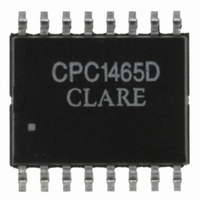
CPC1465D Clare, CPC1465D Datasheet - Page 4

CPC1465D
Manufacturer Part Number
CPC1465D
Description
IC DC TERMINATION 16-SOIC
Manufacturer
Clare
Datasheet
1.CPC1465DTR.pdf
(15 pages)
Specifications of CPC1465D
Function
DC Signal Termination
Interface
ISDN, SHDSL
Number Of Circuits
1
Power (watts)
1W
Operating Temperature
-40°C ~ 85°C
Mounting Type
Surface Mount
Package / Case
16-SOIC
Includes
Optocoupler
Lead Free Status / RoHS Status
Lead free / RoHS Compliant
Current - Supply
-
Voltage - Supply
-
Lead Free Status / Rohs Status
Compliant
Other names
CLA206
CPC1465D
CPC1465D
Available stocks
Company
Part Number
Manufacturer
Quantity
Price
Part Number:
CPC1465D
Manufacturer:
CPCLARE
Quantity:
20 000
Company:
Part Number:
CPC1465DTR
Manufacturer:
PHI
Quantity:
3 000
Part Number:
CPC1465DTR
Manufacturer:
CLARE
Quantity:
20 000
CPC1465
1.4 Electrical Characteristics
Unless otherwise specified, minimum and maximum
values are guaranteed by production testing
requirements. Typical values are characteristic of the
device and are the result of engineering evaluations.
In addition, typical values are provided for
1.4.1 DC Characteristics, Normal Operation
1.4.2 AC Characteristics, Normal Operation
1.4.3 Transition Characteristics, Normal Operation
4
Activate/Non-activate Voltage
Breakover current
DC Voltage drop
DC leakage current
Hold/Release current
Minimum on current
Minimum on current
Minimum on current
Maximum on current
Maximum on current
Photodiode drive current
ac impedance
Linearity distortion
Linearity distortion
Activate time
Deactivate time
Parameter
Parameter
Parameter
For operational templates:
For test conditions:
For activation/deactivation test conditions:
Off State
Active State, 1 mA ≤ I
V
Active State
V
54 V ≤ V
source resistance 200 Ω to 4 kΩ
V
V
V
Active State
200 Hz to 50 kHz
f = 200 Hz to 40 kHz, I
20 mA, V
f = 200 Hz to 40 kHz, I
20 mA, V
(see Figure 7 on page 7)
(see Figure 8 on page 7)
OFF
ON
ON
ON
ON
< 54 V
> 100 V
≤ 70 V
> 70 V
= 20 V
ON
APP
APP
Conditions
Conditions
Conditions
≤ 100 V for 2 seconds,
(see Figure 4 on page 6)
≤ 10.5 V
≤ 12 V
(see Figure 2 on page 5)
-
PP
www.clare.com
SL
PP
SL
SL
≤ 20 mA
= 1 mA to
= 1 mA to
informational purposes only and are not part of the
testing requirements.
All electrical specifications are provided for T
Symbol
Symbol
Symbol
I
I
I
I
I
and
V
I
MAX1
MAX2
V
Z
I
MIN1
MIN2
MIN3
I
I
LKG
D1
D2
H/R
BO
PD
t1
t2
ON
AN
MT
(see Figure 6 on page
and
(see Figure 5 on page
(see Figure 3 on page
Minimum
Minimum
Minimum
30.0
0.1
9.0
0.2
3.0
3.0
20
10
75
50
0
-
-
-
-
-
Typical
Typical
Typical
35.0
12.5
38.4
0.5
1.5
0.5
0.1
0.3
7).
38
45
38
78
70
13
-
-
6).
5).
Maximum
Maximum
Maximum
V
---------- -
1kΩ
39.0
100
1.0
15
70
10
50
ON
1
5
-
-
-
-
-
-
A
=25°C
Unit
Unit
Unit
mA
mA
mA
mA
mA
mA
mA
mA
μA
kΩ
ms
ms
dB
dB
V
V
R02


