ISD1420SI Nuvoton Technology Corporation of America, ISD1420SI Datasheet - Page 7
ISD1420SI
Manufacturer Part Number
ISD1420SI
Description
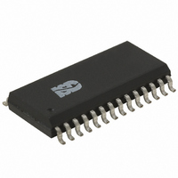
IC VOICE REC/PLAY 20SEC 28-SOIC
Manufacturer
Nuvoton Technology Corporation of America
Series
ISD1400r
Datasheet
1.ISD1416P.pdf
(33 pages)
Specifications of ISD1420SI
Interface
Pushbutton
Filter Pass Band
2.6kHz
Duration
20 Sec
Mounting Type
Surface Mount
Package / Case
28-SOIC (0.300", 7.50mm Width)
Lead Free Status / RoHS Status
Contains lead / RoHS non-compliant
Available stocks
Company
Part Number
Manufacturer
Quantity
Price

Part Number:
ISD1420SI
Manufacturer:
ISD
Quantity:
20 000


PIN NAME
ANA OUT
MIC REF
PLAYE
PLAYL
ANA IN
AGC
[2]
[2]
PIN NO
18
19
20
21
23
24
Microphone Reference : The MIC REF input is the inverting
input to the microphone preamplifier. This provides a noise-
canceling or common-mode rejection input to the device
when connected to a differential microphone.
Automatic Gain Control (AGC) : The AGC dynamically
adjusts the gain of the preamplifier to compensate for the
wide range of microphone input levels. The AGC allows the
full range of sound, from whispers to loud sounds, to be
recorded with minimal distortion. The “attack” time is
determined by the time constant of a 5 KΩ internal resistance
and an external capacitor (C6 on the schematic of section 11,
Figure 5) connected from the AGC pin to V
The “release” time is determined by the time constant of an
external resistor (R5) and an external capacitor (C6)
connected in parallel between the AGC pin and V
ground. Nominal values of 470 KΩ and 4.7 µF give
satisfactory results in most cases.
Analog Input : The analog input pin transfers its signal to the
chip for recording. For microphone inputs, the ANA OUT pin
should be connected via an external capacitor to the ANA IN
pin. This capacitor value, together with the 3.0 KΩ input
impedance of ANA IN, is selected to give additional cutoff at
the low-frequency end of the voice passband. If the desired
input is derived from a source other than a microphone, the
signal can be fed, capacitively coupled, into the ANA IN pin
directly.
Analog Output : This pin provides the preamplifier output to
the user. The voltage gain of the preamplifier is determined
by the voltage level at the AGC pin.
Playback, Level-Activated : When this input signal is held
LOW, a playback cycle is initiated, and playback continues
until PLAYL is pulled HIGH, or an EOM marker is detected.
The device automatically powers down and enters into
standby mode upon completion of a playback cycle.
Playback, Edge-Activated : When a LOW-going transition is
input to this pin, a playback cycle begins. Taking PLAYE
HIGH during a playback cycle will not terminate the current
cycle. Playback continues until an EOM is encountered. Upon
completion of a playback cycle, the device automatically
powers down and enters into standby mode.
- 7 -
Publication Release Date: November 16, 2005
FUNCTION
ISD1400 SERIES
SSA
analog ground.
SSA
Revision 1.3
analog
Related parts for ISD1420SI
Image
Part Number
Description
Manufacturer
Datasheet
Request
R

Part Number:
Description:
MODULE FOR VOICE REC/PLAY 10S
Manufacturer:
Nuvoton Technology Corporation of America
Part Number:
Description:
Manufacturer:
Nuvoton Technology Corporation of America
Datasheet:
Part Number:
Description:
Manufacturer:
Nuvoton Technology Corporation of America
Datasheet:
Part Number:
Description:
Manufacturer:
Nuvoton Technology Corporation of America
Datasheet:
Part Number:
Description:
Manufacturer:
Nuvoton Technology Corporation of America
Datasheet:
Part Number:
Description:
Manufacturer:
Nuvoton Technology Corporation of America
Datasheet:
Part Number:
Description:
Manufacturer:
Nuvoton Technology Corporation of America
Datasheet: