ISD25120S Nuvoton Technology Corporation of America, ISD25120S Datasheet - Page 6
ISD25120S
Manufacturer Part Number
ISD25120S
Description
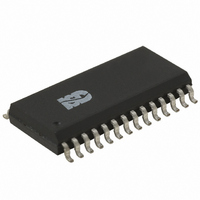
IC VOICE REC/PLAY 120SEC 28-SOIC
Manufacturer
Nuvoton Technology Corporation of America
Series
ISD2500r
Datasheet
1.ISD2560P.pdf
(43 pages)
Specifications of ISD25120S
Interface
Button/MCU
Filter Pass Band
1.7kHz
Duration
120 Sec
Mounting Type
Surface Mount
Package / Case
28-SOIC (0.300", 7.50mm Width)
Lead Free Status / RoHS Status
Contains lead / RoHS non-compliant


6. PIN DESCRIPTION
[2]
[1]
PIN NAME
V
SP+/SP-
Never ground or drive an unused speaker output.
AUX IN
SSA
Connection of speaker outputs in parallel may cause damage to the device.
Ax/Mx
, V
SSD
13, 12
SOIC/
14/15
PDIP
1-10/
1-7
11
PIN NO.
20, 19
TSOP
21/22
8-17/
8-14
18
Address/Mode Inputs: The Address/Mode Inputs have two
functions depending on the level of the two Most Significant Bits
(MSB) of the address pins (A8 and A9).
If either or both of the two MSBs are LOW, the inputs are all
interpreted as address bits and are used as the start address for
the current record or playback cycle. The address pins are inputs
only and do not output any internal address information during the
operation. Address inputs are latched by the falling edge of CE .
If both MSBs are HIGH, the Address/Mode inputs are interpreted as
Mode bits according to the Operational Mode table on page 12.
There are six operational modes (M0…M6) available as indicated in
the table. It is possible to use multiple operational modes
simultaneously. Operational Modes are sampled on each falling
edge of CE , and thus Operational Modes and direct addressing
are mutually exclusive.
Auxiliary Input: The Auxiliary Input is multiplexed through to the
output amplifier and speaker output pins when CE is HIGH, P/ R
is HIGH, and playback is currently not active or if the device is in
playback overflow. When cascading multiple ISD2500 devices, the
AUX IN pin is used to connect a playback signal from a following
device to the previous output speaker drivers. For noise
considerations, it is suggested that the auxiliary input not be driven
when the storage array is active.
Ground : The ISD2500 series of devices utilizes separate analog
and digital ground busses. These pins should be connected
separately through a low-impedance path to power supply ground.
Speaker Outputs : All devices in the ISD2500 series include an on-
chip differential speaker driver, capable of driving 50 mW into 16 Ω
from AUX IN (12.2mW from memory).
[1]
power down. It is therefore not possible to parallel speaker outputs
of multiple ISD2500 devices or the outputs of other speaker drivers.
[2]
between the SP pin and the speaker). These outputs may be used
individually with the output signal taken from either pin. However,
the use of single-end output results in a 1 to 4 reduction in its
output power.
A single-end output may be used (including a coupling capacitor
The speaker outputs are held at V
- 6 -
FUNCTION
ISD2560/75/90/120
SSA
levels during record and
Related parts for ISD25120S
Image
Part Number
Description
Manufacturer
Datasheet
Request
R

Part Number:
Description:
MODULE FOR VOICE REC/PLAY 10S
Manufacturer:
Nuvoton Technology Corporation of America
Part Number:
Description:
Manufacturer:
Nuvoton Technology Corporation of America
Datasheet:
Part Number:
Description:
Manufacturer:
Nuvoton Technology Corporation of America
Datasheet:
Part Number:
Description:
Manufacturer:
Nuvoton Technology Corporation of America
Datasheet:
Part Number:
Description:
Manufacturer:
Nuvoton Technology Corporation of America
Datasheet:
Part Number:
Description:
Manufacturer:
Nuvoton Technology Corporation of America
Datasheet:
Part Number:
Description:
Manufacturer:
Nuvoton Technology Corporation of America
Datasheet: