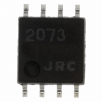
NJM2073M# NJR, NJM2073M# Datasheet

NJM2073M#
Specifications of NJM2073M#
NJM#2073M
Available stocks
Related parts for NJM2073M#
NJM2073M# Summary of contents
Page 1
DUAL LOW VOLTAGE POWER AMPLIFIER ■ GENERAL DESCRIPTION The NJM2073 is a monolithic integrated circuit in 8 lead dual-in-line package,which is designed for dual audio power amplifier in portable radio and handy cassette player. ■ FEATURES ● Operating Voltage ● ...
Page 2
ABSOLUTE MAXIMUM RATINGS PARAMETER Supply Voltage Output Peak Current Power Dissipation Input Voltage Range Operating Temperature Range Storage Temperature Range ■ ELECTRICAL CHARACTERISTICS D-Type (1) BTL Configuration ( Test Circuit Fig.1 ) PARAMETER Operating Voltage Operating Current Output Offset ...
Page 3
Stereo Configuration ( Test Circuit Fig.2 ) PARAMETER Operating Voltage Output Voltage Operating Current Input Bias Current Output Power ( Each Channel ) Total Harmonic Distortion Voltage Gain Channel Balance Input Impedance Equivalent Input Noise Voltage Ripple Rejection Cutoff ...
Page 4
Stereo Configuration ( Test Circuit Fig.2 ) PARAMETER Operating Voltage Output Voltage Operating Current Input Bias Current Output Power ( Each Channel ) Total Harmonic Distortion Voltage Gain Channel Balance Input Impedance Equivalent Input Noise Voltage Ripple Rejection Cutoff ...
Page 5
PARASTIC OSCILLATION PREVEMTING CIRCUIT Put 1Ω+0.22µF on parallel to load,if the load is speaker.Recommend putting 0.1µF and more than 100µF capacitors with good high frequency characteristics in to near ground and supply voltage pins. In BTL operation of less ...
Page 6
The Application Example of Voltage Gain Reduction. ( STEREO ) Fig.6 indicates the application example and Table1 indicates the recommendable value of parts to be attached externally. Table1,Applicating purpose and Recommended Value of Externally parts to be attached. EXTERNAL ...
Page 7
Application for Voltage Gain Reduction ( BTL ) Fig.7 indicates the application example,Table2 shows recommended value of externally attaching parts. Table2 Applicating purpose and Recommended Value of External Part EXTERNAL APPLICATION PURPOSE PARTS R DC condition ground of plus ...
Page 8
TYPICAL CHARACTERISTICS - 8 - Ver.2004-03-01 ...
Page 9
TYPICAL CHARACTERISTICS Ver.2004-03- ...
Page 10
TYPICAL CHARACTERISTICS - 10 - Ver.2004-03-01 ...
Page 11
TYPICAL CHARACTERISTICS Ver.2004-03-01 [CAUTION] The specifications on this databook are only given for information , without any guarantee as regards either mistakes or omissions. The application circuits in this databook are described only to show representative usages of the ...


