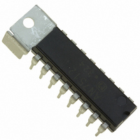
AN7512 Panasonic - SSG, AN7512 Datasheet

AN7512
Specifications of AN7512
Available stocks
Related parts for AN7512
AN7512 Summary of contents
Page 1
... AN7512 Dual 1-W BTL audio power amplifier ■ Overview The AN7512 is an audio power amplifier IC for stereo system. The BTL (Balanced Transformer-Less) method can provide fewer external parts and more easy design for applications. ■ Features • 1-W output (8 Ω) with supply voltage • ...
Page 2
... AN7512 ■ Pin Descriptions Pin No. Description 1 N.C. 2 Standby (standby state if this pin is open.) 3 Ch.1 input 4 Ground (input) 5 Volume (muting off if this pin is open.) 6 Ch.2 input 7 N.C. Ch.2 − output 8 Note) Please do not apply voltage or current to the N.C. pin from outside. ■ Absolute Maximum Ratings ...
Page 3
... W, Vol. = 0.6 V CB2 0.25 W, Vol 0.25 W, Vol Equivalent circuit Open 30 kΩ 10 kΩ 2 kΩ 50 kΩ 12 kΩ 33 kΩ 5 kΩ SDC00032CEB AN7512 = 25°C ± 2°C a Min Typ Max Unit 35 100 mA µ 0.10 0.4 mV[rms ...
Page 4
... AN7512 ■ Terminal Equivalent Circuits (continued) Pin No. Pin name 3 Ch.1 input pin GND 5 Volume pin 6 Ch.2 input pin N.C. 4 Equivalent circuit 50 µA 50 µA 30 kΩ 1 kΩ µA 1 kΩ kΩ 50 µA 50 µA 30 kΩ 1 kΩ Open SDC00032CEB Voltage 1 ...
Page 5
... N.C. 10 GND Ch.2 + output pin 11 1 Ch.1 + output pin 13 1/2 V Equivalent circuit 200 Ω CC 800 Ω 20 kΩ Open 10 200 Ω CC 800 Ω 20 kΩ 200 Ω CC 800 Ω 20 kΩ SDC00032CEB AN7512 Voltage 2. Ω 8 2. Ω 11 5 Ω ...
Page 6
... AN7512 ■ Terminal Equivalent Circuits (continued) Pin No. Pin name 14 GND Ch.1 − output pin 15 1 N.C. ■ Usage Notes • Please avoid the short circuit to V • Please connect the cooling fin with the GND potential. • The thermal shutdown circuit operates at about T cally if the temperature drops. • ...
Page 7
... Both ch. inputs = 10 kΩ 0 STB Vol. = 1.25 V 0.2 0.0 0.01 10 000 100 000 10 SDC00032CEB AN7512 STB Ω Both ch. inputs = 10 kΩ V STB = MUTE I STB Spply voltage V ...
Page 8
... AN7512 ■ Technical Data (continued) • Main characteristics (continued) , THD 0. kHz Ω 400 Hz HPF 30 kHz LPF Both ch. inputs kΩ STB Vol (ch. THD (ch. THD (ch. Supply voltage V RIPPLE 80 Ch.1 (vol.-max.) 70 Ch.2 (vol.-max STB Vol V/1. Ω kHz LPF ...
Page 9
... Input impedance R (Ω) g STB = Ω kΩ Vol 0.5 1.0 1.5 2.0 2.5 Standby voltage V (V) STB Att Ch.2 Ch kHz = 8 Ω 400 Hz HPF 30 kHz LPF = 10 kΩ STB Vol 100 Input voltage V (mV[rms]) IN AN7512 100 000 3.0 1 000 9 ...
Page 10
... AN7512 ■ Technical Data (continued) • Main characteristics (continued) Att f 100 Ch.1, Ch 100 1 000 Frequency f (Hz) CT Ch Ch Supply voltage Ch Ch 100 1 000 Frequency f (Hz 0. Ω kΩ STB Vol 0.01 0.0 10 000 100 000 0. kHz Ω 400 Hz HPF ...
Page 11
... Example of PCB pattern Ch.2 out− Ch.2 out+ Ch.1 out+ Ch.1 out− GND 1 ■ Application Circuit Example Standby Out1 8 Ω 1.0 µF V Volume IN1 SDC00032CEB TAB TAB GND (input) V (ch.2) IN Volume V (ch.1) IN Standby Out2 8 Ω 1.0 µF V IN2 AN7512 11 ...
Page 12
Request for your special attention and precautions in using the technical information and (1) If any of the products or technical information described in this book exported or provided to non-residents, the laws and regulations of the ...


