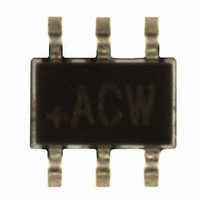
MAX4090AAXT+T Maxim Integrated Products, MAX4090AAXT+T Datasheet - Page 10

MAX4090AAXT+T
Manufacturer Part Number
MAX4090AAXT+T
Description
IC VIDEO BUFFER SC70-6
Manufacturer
Maxim Integrated Products
Datasheet
1.MAX4090AAXTT.pdf
(17 pages)
Specifications of MAX4090AAXT+T
Applications
Buffer
Number Of Circuits
1
-3db Bandwidth
55MHz
Slew Rate
275 V/µs
Current - Supply
6.5mA
Current - Output / Channel
85mA
Voltage - Supply, Single/dual (±)
2.7 V ~ 5.5 V
Mounting Type
Surface Mount
Package / Case
6-TSSOP, SC-88, SOT-363
Number Of Channels
1
Operating Supply Voltage
5.5 V
Supply Current
6.5 mA
Minimum Operating Temperature
- 40 C
Maximum Operating Temperature
+ 125 C
Bandwidth
55 MHz
Maximum Dual Supply Voltage
5.25 V
Minimum Dual Supply Voltage
2 V
Supply Voltage (max)
5.5 V
Supply Voltage (min)
2.7 V
Lead Free Status / RoHS Status
Lead free / RoHS Compliant
Other names
MAX4090AAXT+TTR
3V/5V, 6dB Video Buffer with Sync-Tip Clamp
and 150nA Shutdown Current
Figure 5. Frequency Response for R1 = R2 = 150 Ω
Figure 6. Sag Correction Configuration
10
CURRENT
______________________________________________________________________________________
VIDEO
DAC
-10
-20
-30
-40
-50
-60
0
0.1
150Ω
R1
FREQUENCY RESPONSE
FREQUENCY (MHz)
1
3-POLE RECONSTRUCTION LPF
C1
120pF
4.7μH
10
6.8pF
L1
C3
120pF
C2
100
R2
150Ω
49.9Ω
R
V
IS
CC
The MAX4090 operates from single 2.7V to 5.5V sup-
ply. Bypass the supply with a 0.1µF capacitor as close
to the pin as possible. Maxim recommends using
microstrip and stripline techniques to obtain full band-
width. To ensure that the PC board does not degrade
the device’s performance, design it for a frequency
greater than 1GHz. Pay careful attention to inputs and
outputs to avoid large parasitic capacitance. Whether
or not you use a constant-impedance board, observe
the following design guidelines:
• Do not use wire-wrap boards; they are too inductive.
• Do not use IC sockets; they increase parasitic
• Use surface-mount instead of through-hole compo-
• Use a PC board with at least two layers; it should be
• Keep signal lines as short and as straight as possible.
capacitance and inductance.
nents for better, high-frequency performance.
as free from voids as possible.
Do not make 90° turns; round all corners.
0.1μF
C4
Layout and Power-Supply Bypassing
SHDN
IN
MAX4090
GND
V
CC
OUT
FB
22μF
22μF
C5
C6
C7
1μF
75Ω
R3
V
CC
V
OUT


