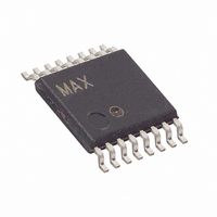
MAX4028EUE+ Maxim Integrated Products, MAX4028EUE+ Datasheet - Page 7

MAX4028EUE+
Manufacturer Part Number
MAX4028EUE+
Description
IC AMP VIDEO MUX 2:1 16-TSSOP
Manufacturer
Maxim Integrated Products
Datasheet
1.MAX4028EUET.pdf
(13 pages)
Specifications of MAX4028EUE+
Applications
2:1 Multiplexer-Amplifier
Number Of Circuits
3
-3db Bandwidth
210MHz
Slew Rate
300 V/µs
Current - Supply
29mA
Current - Output / Channel
30mA
Voltage - Supply, Single/dual (±)
4.5 V ~ 5.5 V
Mounting Type
Surface Mount
Package / Case
16-TSSOP
Lead Free Status / RoHS Status
Lead free / RoHS Compliant
Figure 1. MAX4029 Functional Diagram
CLAMP/KEY_2
CLAMP/KEY_3
CLAMP/KEY_4
MAX4028
KEYREF
15
16
—
IN1A
IN1B
IN2A
IN2B
IN3A
IN3B
IN4A
IN4B
A/B
PIN
MAX4029
CLAMP/
CLAMP/
CLAMP/
CLAMP/
CLAMP/
CLAMP/
CLAMP
CLAMP
CLAMP
CLAMP
CLAMP
CLAMP
CLAMP
CLAMP
KEY
KEY
KEY
KEY
KEY
KEY
Multiplexer-Amplifiers with Input Clamps
18
20
19
_______________________________________________________________________________________
VOLTAGE
CLAMP
CLAMP/KEY_4
GND
DISABLE
1kΩ
1kΩ
1kΩ
1kΩ
NAME
OUT1
MAX4029
V
CC
1kΩ
1kΩ
1kΩ
1kΩ
Amplifier Output 1
Disable Input. Pull DISABLE high for normal operation. Drive DISABLE low to disable
all outputs.
Output 4 Clamp or Key-Clamp Input. Drive CLAMP/KEY_4 high to clamp OUT4.
Drive CLAMP/KEY_4 low to key clamp OUT4.
OUT1
OUT2
OUT3
OUT4
DISABLE
The MAX4028/MAX4029 are 5V, triple/quad, 2:1 voltage-
feedback multiplexer-amplifiers with input clamps and a
fixed gain of +2V/V (6dB). Channel 1 (IN1A and IN1B)
inputs are clamped to the video sync tip of the input
IN1_ channel, while the remaining inputs can be
clamped to either the video sync tip of the respective
input channel (IN_A and IN_B) or the video sync of
channel 1 (IN1_). The latter is referred to as a key
clamp and is pin selectable. Selectable clamp/key-
clamp inputs and fixed-gain video output buffers make
the MAX4028/MAX4029 ideal for video-source switching
applications such as automotive entertainment systems,
video projectors, and displays/TVs. Both devices have
20ns channel switching times and low ±10mV
ing transients, making them ideal for both high-speed
video switching applications such as OSD insertion.
The MAX4028/MAX4029 have a -3dB large-signal (2V
bandwidth of 130MHz, a -3dB small-signal bandwidth of
210MHz, and a 300V/µs slew rate. Low differential gain
and phase errors of 0.2% and 0.4°, respectively, make
these devices ideal for broadcast video applications.
The MAX4028/MAX4029 have AC-coupled inputs, with
either a sync tip or key clamp to provide bias for the
video signal. Channel 1 of the MAX4028/MAX4029
always has a sync tip clamp at the input, while the
remaining channels are selectable as either sync tip or
key clamps to accommodate the various video wave-
forms (see the
Formats section). The value of the sync-tip clamp voltage
is set internally for the lowest value, consistent with linear
operation, and cannot be adjusted. The key-clamp volt-
age is adjustable, to compensate for variations in the
voltage between component video inputs such as Linear
RGB, YPbPr, and Y-C, by varying R
clamp voltage can be computed from:
Triple/Quad, 2:1 Video
V
Key-Clamp
Pin Description (continued)
FUNCTION
Clamp/Key-Clamp Settings for Video
= 0.40 + 2000/[(5000 x R
(5000 + R
Detailed Description
Sync Tip and Key Clamps
KEYREF
)]
KEYREF
KEYREF
P-P
. The key-
switch-
) /
P-P
7
)


