1-5520250-1 TE Connectivity, 1-5520250-1 Datasheet
1-5520250-1
Specifications of 1-5520250-1


Related parts for 1-5520250-1


1-5520250-1 Summary of contents
Page 1
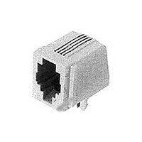
... Modular Telephone Plugs and Jacks designed for Printed Circuit Board (PCB) mounting. 1.2. Qualification When tests are performed on the subject product line, procedures specified in Figure 1 shall be used. All inspections shall be performed using the applicable inspection plan and product drawing. 1.3. Qualification Test Results Successful qualification testing on the subject product line was completed on 19May89 ...
Page 2
... Product Drawing. 3.2. Materials Materials used in the construction of this product shall be as specified on the applicable product drawing. 3.3. Ratings ! Current, per pin: 1.5 amperes alternating current maximum at 25° C derated to 0.2 amperes maximum at 70° C ambient ! Derating Curve: ! Voltage: 150 volts AC maximum ! Temperature: -40 to 85° C ...
Page 3
... EIA-364-70, Method 1. Subject mated plug and jack to temperature rise at rated current. TE Spec 109-51, Condition B, Method 2. Subject mated plug and jack to 500 cycles at 125% of rated current for 15 minutes ON and 15 minutes OFF. TE Spec 109-90. Measure radiated response from unshielded mated jack and plug ...
Page 4
... Pulse to have 10/1000 microsecond shape and 1000 volt peak. EIA-364-28, Test Condition I. Subject mated plug and jack mounted on PCB to sinusoidal vibration for 15 minutes in each of 3 mutually perpendicular axis. EIA-364-9. Subject plug and jack to 750 mating and unmating cycles at the rate of 500 cycles per hour with latch inoperative ...
Page 5
... Current cycling Shielding effectiveness Surge Vibration Durability Mating force Unmating force Plug retention in jack Pull Jack retention to PCB Thermal shock High humidity/temperature cycling (a) See paragraph 4.1.A. NOTE (b) Numbers indicate sequence in which tests are performed. Rev G Test Group ( Test Sequence (b) ...
Page 6
... Acceptance Acceptance is based on verification that the product meets the requirements of Figure 1. Failures attributed to equipment, test setup, or operator deficiencies shall not disqualify the product. When product failure occurs, corrective action shall be taken and samples resubmitted for qualification. ...
Page 7
... Millivolt drop (resistance) due to the 6 inch wire length shall be subtracted from all readings. NOTE Rev G Figure 3 Termination Resistance Measurement Points Figure 4 Plug and Jack Retention Forces 108-1163 ...