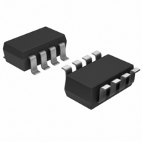
MAX9018AEKA+T Maxim Integrated Products, MAX9018AEKA+T Datasheet - Page 12

MAX9018AEKA+T
Manufacturer Part Number
MAX9018AEKA+T
Description
IC COMPARATOR DUAL SOT23-8
Manufacturer
Maxim Integrated Products
Series
Beyond-the-Rails™r
Type
with Voltage Referencer
Datasheet
1.MAX9020EKAT.pdf
(17 pages)
Specifications of MAX9018AEKA+T
Number Of Elements
2
Output Type
CMOS, Open-Drain, Rail-to-Rail
Voltage - Supply
1.8 V ~ 5.5 V
Mounting Type
Surface Mount
Package / Case
SOT-23-8
Lead Free Status / RoHS Status
Lead free / RoHS Compliant
Other names
MAX9018AEKA+T
MAX9018AEKA+TTR
MAX9018AEKA+TTR
Many comparators oscillate in the linear region of oper-
ation because of noise or undesired parasitic feed-
back. Oscillations can occur when the voltage on one
input is equal or very close to the voltage on the other
input. The MAX9015–MAX9020 have internal 4mV hys-
teresis to counter parasitic effects and noise.
The hysteresis in a comparator creates two trip points:
one for the rising input voltage (V
falling input voltage (V
between the trip points is the hysteresis (V
the comparator’s input voltages are equal, the hystere-
sis effectively causes one comparator input to move
quickly past the other, thus taking the input out of the
region where oscillation occurs. Figure 1 illustrates the
case in which the comparator’s inverting input has a
fixed voltage applied, and the noninverting input is var-
ied. If the inputs were reversed, the figure would be the
same, except with an inverted output.
The MAX9015/MAX9017/MAX9019 feature a built-in
4mV hysteresis band (V
be generated with three resistors using positive feed-
back (Figure 2). Use the following procedure to calcu-
late resistor values:
1) Select R3. Input bias current at IN_+ is less than
2) Choose the hysteresis band required (V
3) Calculate R1 according to the following equation:
SOT23, Dual, Precision, 1.8V, Nanopower
Comparators With/Without Reference
12
2nA, so the current through R3 should be at least
0.2µA to minimize errors caused by input bias cur-
rent. The current through R3 at the trip point is
(V
put states in solving for R3 yields two formulas: R3
= V
er of the two resulting resistor values. For example,
when using the MAX9017 (V
= 5V, and if we choose I
resistor values are 6.2MΩ and 19MΩ. Choose a
6.2MΩ standard value for R3.
example, choose 50mV.
For this example, insert the values:
______________________________________________________________________________________
REF
REF
- V
/IR3 or R3 = (V
R
OUT
1
=
(MAX9015/MAX9017/MAX9019)
)/R3. Considering the two possible out-
6 2
R
.
1
M
=
Ω
R
THF
⎛
⎜
⎝
3
HB
CC
50
⎛
⎜
⎝
) (Figure 1). The difference
5
). Additional hysteresis can
Additional Hysteresis
V
V
mV
V
HB
CC
- V
R3
(Push-Pull Outputs)
Internal Hysteresis
⎞
⎟ =
⎠
REF
⎞
⎟
⎠
REF
= 0.2µA, then the two
THR
12
)/I
= 1.24V) and V
R3
k
) and one for the
Ω
. Use the small-
HB
HB
). For this
). When
CC
4) Choose the trip point for V
5) Calculate R2 as follows:
Figure 1. Threshold Hysteresis Band
Figure 2. MAX9015/MAX9017/MAX9019 Additional Hysteresis
OUT
IN+
IN-
R
2
where V
threshold voltage at which the comparator switches
its output from low to high as V
trip point. For this example, choose 3V.
For this example, choose a 44.2kΩ standard value.
V
V
V
IN
=
THR
THF
⎡
⎢
⎢
⎣
⎛
⎜
⎝
( .
1 24
R
2
THR
R1
=
V X
V
V
3 0
HB
.
THR
⎡
⎢
⎢
⎣
is the trip point for V
⎛
⎜
⎝
V
R2
62
V
REF
k
V
>
Ω
THR
)
V
X R
⎞
⎟ −
⎠
THRESHOLDS
V
REF
REF
HYSTERESIS
1
1
⎞
⎟ −
⎠
⎛
⎜
⎝
BAND
62
1
⎛
⎜
⎝
R3
1
k
1
⎛
⎜
⎝
IN
Ω
R
1
+
1
⎞
⎟ −
⎠
⎞
⎟ −
⎠
rising (V
V
V
V
V
CC
V
CC
EE
HB
CC
⎛
⎜
⎝
⎛
⎜
⎝
6 2
IN
R
IN
MAX9015
MAX9017
MAX9019
1
.
3
⎞
⎟
⎠
1
M
⎞
⎟
⎠
rising. This is the
rises above the
⎤
⎥
⎥
⎦
OUT
Ω
THR
⎞
⎟
⎠
⎤
⎥
⎥
⎦
) such that:
=
43 99
.
k
Ω


