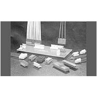
6-1123723-3 TE Connectivity, 6-1123723-3 Datasheet - Page 2

6-1123723-3
Manufacturer Part Number
6-1123723-3
Description
Manufacturer
TE Connectivity
Specifications of 6-1123723-3
Product Line
Economy Power
Product Type
Connector
Connector Type
Header
Pcb Mounting Orientation
Vertical
Pcb Mount Retention
Without
Pcb Mount Alignment
Without
Termination Method To Pc Board
Through Hole - Solder
Sealed
No
Mating Retention Type
Latching
Contact - Rated Current (a)
7.5
Operating Voltage Reference
AC
Operating Voltage (vac)
250
Tail Orientation
In-line
Tail Length (mm [in])
3.7 [0.146]
Profile Height (y-axis) (mm [in])
8.50 [0.3346]
Centerline (mm [in])
3.96 [0.156]
Header Type
Unshrouded
Number Of Positions
3
Selectively Loaded
No
Mating Retention
With
Number Of Rows
1
Length (x-axis) (mm [in])
11.82 [0.4653]
Width (z-axis) (mm [in])
10.70 [0.421]
Contact Type
Pin
Contact Base Material
Brass
Contact Plating, Mating Area, Material
Tin
Contact Plating, Mating Area, Thickness (µm [?in])
0.8 [31.5]
Contact Design
Square Post
Tail Plating Material
Tin
Tail Plating, Thickness (µm [?in])
0.8 [31.46]
Connector Style
Plug
Housing Material
PBT
Housing Color
Green
Mating Alignment
With
Ul Flammability Rating
UL 94V-0
Rohs/elv Compliance
RoHS compliant, ELV compliant
Lead Free Solder Processes
Wave solder capable to 240°C, Wave solder capable to 260°C, Wave solder capable to 265°C
Rohs/elv Compliance History
Converted to comply with RoHS directive
Operating Temperature (°c [°f])
-25 – +105 [-13 – +221]
Applies To
Printed Circuit Board
Pcb Thickness, Recommended (mm [in])
1.60 [0.063]
Contact Transmits (typical Application)
Power
3.3.
3.4.
3.5.
Initial examination of product.
Final examination of product.
Low Level Contact Resistance
(LLCR).
Insulation resistance.
Withstanding voltage.
Temperature rise vs current.
Random vibration.
Rev O5
Ratings
!
!
!
Performance and Test Description
Product is designed to meet the electrical, mechanical and environmental performance requirements
specified in Figure 1. Unless otherwise specified, all tests shall be performed at ambient environmental
conditions.
Test Requirements and Procedures Summary
Test Description
Voltage: 600 volts AC
Current: See Figure 4 for applicable current carrying capability. Maximum rated current that can
be carried by this product is limited by maximum operating temperature of the housings (105° C)
and temperature rise of the housings (30° C). Variab les to be considered for each application are:
wire size, connector size, contact material, ambient temperature, and printed circuit board design.
Temperature: -55 to 105° C
Meets requirements of product
drawing and Application
Specification 114-13265.
Meets visual requirements.
10 milliohms maximum initial.
20 milliohms maximum final.
1000 megohms minimum initial.
500 megohms minimum final.
One minute hold with no breakdown
or flashover.
30° C maximum temperatur e rise at
specified current.
No discontinuities of 1 microsecond
or longer duration.
See Note.
Figure 1 (continued)
MECHANICAL
ELECTRICAL
Requirement
EIA-364-18.
Visual and dimensional (C of C)
inspection per product drawing.
EIA-364-18.
Visual inspection.
EIA-364-23.
Subject specimens to 100
milliamperes maximum and 20
millivolts maximum open circuit
voltage.
See Figure 3.
EIA-364-21.
500 volts DC, 2 minute hold.
Test between adjacent contacts.
EIA-364-20, Condition I.
1500 volts AC at sea level.
Test between adjacent contacts.
EIA-364-70, Method 1.
Stabilize at a single current level
until 3 readings at 5 minute intervals
are within 1° C.
See Figure 4.
EIA-364-28, Test Condition VII,
Condition Letter D.
Subject mated specimens to 3.10
G's rms between 20 to 500 Hz.
Fifteen minutes in each of 3
mutually perpendicular planes.
Procedure
108-2297
2 of 6


