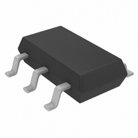
LT6700HVHS6-3#TRPBF Linear Technology, LT6700HVHS6-3#TRPBF Datasheet - Page 14

LT6700HVHS6-3#TRPBF
Manufacturer Part Number
LT6700HVHS6-3#TRPBF
Description
IC COMP DUAL 400MV REF TSOT23-6
Manufacturer
Linear Technology
Series
Over-The-Top®r
Type
General Purposer
Datasheet
1.LT6700CS6-3TRMPBF.pdf
(20 pages)
Specifications of LT6700HVHS6-3#TRPBF
Number Of Elements
2
Output Type
Open Collector
Voltage - Supply
1.4 V ~ 18 V
Mounting Type
Surface Mount
Package / Case
SOT-23-6 Thin, TSOT-23-6
Lead Free Status / RoHS Status
Lead free / RoHS Compliant
Available stocks
Company
Part Number
Manufacturer
Quantity
Price
Part Number:
LT6700HVHS6-3#TRPBFLT6700HVHS6-3#TRMPBF
Manufacturer:
LINEAR/凌特
Quantity:
20 000
LT6700/LT6700HV
applicaTions inForMaTion
The LT6700-1/LT6700-2/LT6700-3/LT6700HV-1/
LT6700HV-2/LT6700HV-3 devices are a family of dual
micropower comparators with a built-in 400mV refer-
ence. Features include wide supply voltage range (1.4V to
18V), Over-The-Top input and output range, 2% accurate
rising input threshold voltage and 6.5mV typical built-in
hysteresis. The comparator’s open-collector outputs can
sink up to 40mA typical.
Internal Reference
Each of the comparator sections has one input available
externally, with the three versions of the part differing by
the polarity of those available inputs (i.e., inverting or
noninverting). The other comparator inputs are connected
internally to the 400mV reference. The rising input threshold
voltage of the comparators is designed to be equal to that
of the reference (i.e., ≈ 400mV). The reference voltage is
established with respect to the device GND connection.
Hysteresis
Each comparator has built-in 6.5mV (typical) hysteresis to
simplify designs, ensure stable operation in the presence
of noise at the inputs, and to reject supply rail noise that
might be induced by state change load transients. The
hysteresis is designed such that the falling input threshold
voltage is nominally 393.5mV. External positive feedback
circuitry can be employed with noninverting comparator
inputs to increase effective hysteresis if desired, but such
circuitry will provide an apparent effect on both the rising
and falling input thresholds (the actual internal thresholds
remain unaffected).
Comparator Inputs
A comparator input can swing from ground to 18V (36V
for LT6700HV), regardless of the supply voltage used. The
typical input current for inputs well above threshold (i.e.,
>800mV) is a few pA leaking into an input. With decreasing
input voltage, a small bias current begins to be drawn out
of the input, reaching a few nA when at ground potential.
The input may be forced 100mV below ground without
causing an improper output, though some additional bias
current will begin to flow from the parasitic ESD input pro-
tection diode. Inputs driven further negative than 100mV
below ground will not cause comparator malfunction or
damage (provided the current is limited to 10mA), but
the accuracy of the reference cannot be guaranteed, in
which case the output state of the alternate comparator
may be affected.
Comparator Outputs
The comparator outputs are open collector and capable
of sinking 40mA typical. Load currents are directed out
the GND pin of the part. The output off-state voltage may
range between –0.3V and 18V (36V for LT6700HV) with
respect to ground, regardless of the supply voltage used.
When the output high state bias voltage is above 18V, a
100k minimum pull-up resistor is required and total load
capacitor must be less than 100nF . If the output high state
is above 18V, caution must be taken to prevent a short
from the output directly to the bias voltage, even if the
output is in the off state. As with any open-collector device,
the outputs may be tied together to implement wire-AND
logic functions.
Power Supplies
The comparator family core circuitry operates from a single
1.4V to 18V supply. A minimum 0.1µF bypass capacitor
is required between the V
load is connected to the supply rail near the part and the
output is sinking more than 5mA, a 1µF bypass capaci-
tor is recommended. The voltage reference built into the
LT6700 can be susceptible to high noise on the supply
line, particularly noise that is less than 50kHz and larger
than 20mV
comparator output in the presence of high supply noise,
an RC filter should be used to reduce the noise. This filter
can be created simply by adding a series R between the
system supply and the LT6700 V
capacitor to create a lowpass response. It is recommended
that the filter have a time constant:
Where V
t
This filter will also increase the start-up time of the LT6700
by reducing the rate at which the supply can change. When
RC
t
RC
is milliseconds.
> V
N
N
is the peak-peak supply noise in millivolts and
P-P
/100
. In order to reduce the probability of a false
S
pin and GND. When an output
S
pin, using the decoupling
6700123fg


