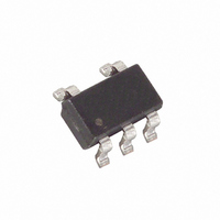
LMX331AUK-T Maxim Integrated Products, LMX331AUK-T Datasheet - Page 8

LMX331AUK-T
Manufacturer Part Number
LMX331AUK-T
Description
IC COMPARATOR GP LV TINY SOT23-5
Manufacturer
Maxim Integrated Products
Type
General Purposer
Datasheet
1.LMX393HAKAT.pdf
(9 pages)
Specifications of LMX331AUK-T
Number Of Elements
1
Output Type
Open Drain
Voltage - Supply
1.8 V ~ 5.5 V
Mounting Type
Surface Mount
Package / Case
SC-74A, SOT-753
Lead Free Status / RoHS Status
Contains lead / RoHS non-compliant
1) Find output voltage when output is high:
2) Find the trip points of the comparator using these
where V
parator switches its output from high to low as V
above the trip point, and V
which the comparator switches its output from low to
high as V
3) The hysteresis band will be:
In this example, let V
50nA, R
Select R2. In this example, we will choose 1kΩ.
Select V
Solve for R1:
General-Purpose, Low-Voltage,
Single/Dual/Quad, Tiny-Pack Comparators
Figure 2. Adding Hysteresis with External Resistors
8
V
V
V
formulas:
V
V
V
0.050V = 5(1000 / (R1 + 1000)) V
REF
OUT(HIGH)
_______________________________________________________________________________________
IN
TH
TL
HYST
V
= V
= V
L
HYST
TH
HYST
IN
R2
= 5.1kΩ:
= V
V
REF
REF
is the threshold voltage at which the com-
drops below the trip point.
V
TH
V
. In this example, we will choose 50mV.
OUT(HIGH)
TL
OUT(HIGH)
= V
= 5.0V - (50
(1 - (R2 / (R1 + R2)))
+ ((V
= 2.5V + 2.5V(R2 / (R1 + R2))
= 2.5V(1 - (R2 / (R1 + R2)))
TH
IN+
IN-
OUT(HIGH)
- V
R1
DD
TL
(R2 / (R1 + R2)) V
= V
= 5V, V
= V
TL
DD
10
is the threshold voltage at
DD
V
V
V
-9
- I
- V
DD
DD
SS
(R2 / (R1 + R2))
LOAD
REF
REF
5.1 10
)R2) / (R1 + R2)
LMX331
= 2.5V, I
R
L
R
OUT
L
3
Ω) ≈ 5.0V
LOAD
IN
V
OUT
rises
=
where R1 ≈ 100kΩ, V
Choose R1 and R2 to be large enough as not to exceed
the amount of current the reference can supply.
Choose R
current, yet small enough to supply the necessary cur-
rent to drive the load. R
10kΩ.
Use 0.1µF bypass capacitors from V
imize performance, minimize stray inductance by
putting this capacitor close to the V
ing trace lengths. For slow-moving input signals (rise
time > 1ms), use a 1nF capacitor between IN+ and IN-
to reduce high-frequency noise.
LMX331/LMX331H TRANSISTOR COUNT: 112
LMX393/LMX393H TRANSISTOR COUNT: 211
LMX339/LMX339H TRANSISTOR COUNT: 411
For the latest package outline information and land patterns, go
to www.maxim-ic.com/packages. Note that a “+”, “#”, or “-” in
the package code indicates RoHS status only. Package draw-
ings may show a different suffix character, but the drawing per-
tains to the package regardless of RoHS status.
PACKAGE
14 TSSOP
5 SOT23
8 SOT23
14 SOIC
8 µMAX
5 SC70
The source current required is V
The sink current is (V
TYPE
L
to be large enough to avoid drawing excess
PACKAGE
U16M+1
CODE
K8F+4
U5+2
U8+1
X5+1
S8+4
Board Layout and Bypassing
TH
Package Information
= 2.525V, and V
OUT(HIGH)
L
should be between 1kΩ and
DOCUMENT
Chip Information
21-0076
21-0057
21-0078
21-0036
21-0066
21-0041
NO.
- V
REF
DD
DD
REF
/ (R1 + R2).
to V
TL
pin and reduc-
PATTERN NO.
) (R1 + R2).
= 2.475V.
SS
90-0188
90-0174
90-0176
90-0092
90-0117
90-0041
LAND
. To max-


