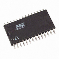
TDA4470-MFLG3Y Atmel, TDA4470-MFLG3Y Datasheet - Page 11

TDA4470-MFLG3Y
Manufacturer Part Number
TDA4470-MFLG3Y
Description
IC SOUND PROC VIDEO-IF 28SOIC
Manufacturer
Atmel
Type
Videor
Datasheet
1.TDA4470-MFLG3Y.pdf
(24 pages)
Specifications of TDA4470-MFLG3Y
Applications
VIF/SIF Signal Processing
Mounting Type
Surface Mount
Package / Case
28-SOIC (7.5mm Width)
Lead Free Status / RoHS Status
Lead free / RoHS Compliant
7. Electrical Characteristics (Continued)
V
4803C–TVVCR–10/05
Parameters
Differential phase error
Intermodulation 1.07 MHz
Video signal-to-noise ratio
Residual vision carrier
fundamental wave 38.9 MHz
and second harmonic
77.8 MHz
Lower limiting level
Upper limiting level
Ripple rejection
Standard Switch
Control voltage for mode 1:
negatively modulated video-IF
signals and AM/NICAM sound
Control voltage for mode 2:
positively modulated video-IF
signals and AM/L-NICAM
sound
Switching current
AFC Output
Control slope
Frequency drift by temperature
Output voltage
- upper limit
- lower limit
Output current
Notes:
S
= +5V, T
1. This parameter is given as an application information and has not been tested during production.
2. In VCR mode, the VIF- and SIF path is switched off.
3. The adjustment of the turn over point (delayed tuner AGC) with the external resistor R
4. Resonance circuit of VCO (f
5. The oscillator drift is related to the picture carrier frequency, given that the external LC circuit is temperature-compensated.
6.
7. Without external control at pin 13 the IC automatically operates in mode 1:
8. Without a control voltage at pin 19 the falling AFC curve is automatically selected.
9. With an open circuit at pin 14 the L’ switch is not active.
10. Picture carrier PC = 38.9 MHz; sound carrier SC
11. Sound carrier SC = 32.4 MHz, modulated with f
12. Without a control voltage at pin 3 the SIF input 1 is automatically selected.
amb
possible.
Coil LVCO with unloaded Q-factor Q
(e.g., TOKO
input signal conditions: picture carrier = 0 dB, colour carrier = –6 dB, sound carrier = –24 dB.
PC/SC
= +25°C; reference point pin 4 (9, 16), unless otherwise specified.
(1.07) = 20 log (4.43 MHz component/1.07 MHz component);
negatively modulated video-IF signals and FM/NICAM sound signals.
1
=13 dB; PC/SC
®
coil 7 KM, 292 XNS - 4051Z).
(6)
Weighted, CCIR-567
Below synchronous level
Above ultra white level
Pin 23/pin 12
(7)
Related to the picture carrier
frequency
Test Conditions
2
= 20 dB; PC unmodulated (equivalent to synchronous peak level).
o
= 38.9 MHz): CVCO = 8.2 - 10 pF,
(1)
o
60 for an oscillator voltage
mod
1
= 33.4 MHz, SC
= 1 kHz, m = 54%; V
Pin
13
22
(1.07) value related to black-white signal
2
= 33.16 MHz;
100 mV
Symbol
V
V
V
V
I
S/
V
V
RR
I
IN
AFC
SW
res1
AFC
I/
SW
SW
IM
P
lim1
lim2
N
=10 mV
f
RMS
at pin 20 - 21
V
S
Min.
2.0
52
56
35
– 0.4
0
TOP
or external voltage V
±100
Typ.
0.25
±0.2
400
600
0.7
60
60
2
2
TDA4470
Max.
0.8
0.6
0.4
10
V
5
S
TOP
µA/kHz
is
Unit
deg
mV
mV
mV
mA
dB
dB
dB
µA
%
V
V
V
V
11


