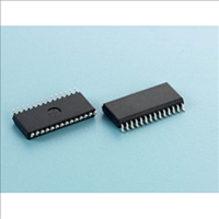
APU3146 Advanced Power Electronics Corp., APU3146 Datasheet - Page 8

APU3146
Manufacturer Part Number
APU3146
Description
The APU3046 IC combines a Dual synchronous Buck controller and a linear regulator controller, providing a cost-effective, high performance and flexible solution for multi-output applications
Manufacturer
Advanced Power Electronics Corp.
Datasheet
1.APU3146.pdf
(28 pages)
Specifications of APU3146
Vin(min)
0.8
Vin(max)
16
Vout(min)
0.8
Vout(max)
5
Iout(max)
30
Frequency
200~500KHz
Power Good
?
Package
28-Pin TSSOP ,28-Pin SOIC
APU3146
The soft-start is part of Over Current Protection scheme,
during the overload or short circuit condition the external
soft start capacitors will be charged and discharged in
certain slope rate to achieve the hiccup mode function.
Out-of-Phase Operation
The APU3146 drives its two output stages 180 out-of-
phase. In 2-phase configuration, the two inductor ripple
currents cancel each other and result in a reduction of
the output current ripple and yield a smaller output ca-
pacitor for the same ripple voltage requirement.
In single input voltage applications, the input ripple cur-
rent reduces. This result in much smaller input capacitor's
RMS current and reduces the input capacitor quantity.
Over-Current Protection
The APU3146 can provide two different schemes for Over-
Current Protection (OCP). When the pin Hiccup is pulled
high, the OCP will operate in hiccup mode. In this mode,
during overload or short circuit, the outputs enter hiccup
mode and stay in that mode until the overload or short
circuit is removed. The converter will automatically re-
cover.
When the Hiccup pin is pulled low, the OCP scheme
will be changed to the latch up type, in this mode the
converter will be turned off during Overcurrent or short
circuit. The power needs to be recycled for normal
operation.
Each phase has its own independent OCP circuitry.
The OCP is performed by sensing current through the
R
external resistor (R
and the drain of low side MOSFET (Q2) which sets the
current limit set point.
If using one soft start capacitor in dual configuration for a
precise power up the OCP needs to be set to latch mode.
For a given start up time, the soft-start capacitor can be
calculated by:
DS(ON)
Figure 8 - 3uA current source for discharging soft
of low side MOSFET. As shown in Figure 9, an
start-capacitor during Hiccup mode
SS1 / SD
C
SET
SS
20
) is connected between OCSet pin
≅ 25µA×T
25uA
3uA
START
Hiccup
/1V
The internal current source develops a voltage across
R
tor current flows through the Q2 and results a voltage
which is given by:
The critical inductor current can be calculated by set-
ting:
The value of R
circuit to ensure that the Over Current Protection
circuit activates as expected. The APU3146 current
limit is designed primarily as disaster preventing, "no
blow up" circuit, and is not useful as a precision
current regulator.
In two independent mode, the output of each channel
is protected independently which means if one output
is under overload or short circuit condition, the other
output will remain functional. The OCP set limit can be
programmed to different levels by using the external
resistors. This is valid for both hiccup mode and latch
up mode.
In 2-phase configuration, the OCP's output depends on
any one channel, which means as soon as one
channel goes to overload or short circuit condition the
output will enter either hiccup or latch-up, dependes on
status of Hiccup pin.
SET
Hiccup
Control
Figure 9 - Diagram of the over current sensing.
. When the low side switch is turned on, the induc-
V
V
I
SET
OCSET
OCSET
APU3146
= I
L(CRITICAL)
= I
= I
OCSET
OCSET
SET
I
OCSET
should be checked in an actual
×R
×R
=
SET
SET
R
R
OCSet
SET
DS(ON)
-R
- R
×I
DS(ON)
DS(ON)
OCSET
R
SET
×i
×I
L
L
= 0
Q1
Q2
---(2)
L1
---(3)
V
8/28
OUT


