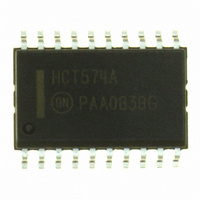
MC74HCT574ADWG ON Semiconductor, MC74HCT574ADWG Datasheet - Page 2

MC74HCT574ADWG
Manufacturer Part Number
MC74HCT574ADWG
Description
IC FLIP FLOP OCT D 3ST 20-SOIC
Manufacturer
ON Semiconductor
Series
74HCTr
Type
D-Type Busr
Datasheet
1.MC74HCT574ADTR2G.pdf
(7 pages)
Specifications of MC74HCT574ADWG
Function
Standard
Output Type
Tri-State Non Inverted
Number Of Elements
1
Number Of Bits Per Element
8
Frequency - Clock
30MHz
Delay Time - Propagation
30ns
Trigger Type
Positive Edge
Current - Output High, Low
6mA, 6mA
Voltage - Supply
4.5 V ~ 5.5 V
Operating Temperature
-55°C ~ 125°C
Mounting Type
Surface Mount
Package / Case
20-SOIC (7.5mm Width)
Number Of Circuits
8
Logic Family
74HCT
Logic Type
D-Type Flip-Flop
Polarity
Non-Inverting
Input Type
Single-Ended
Propagation Delay Time
30 ns
High Level Output Current
- 6 mA
Supply Voltage (max)
5.5 V
Maximum Operating Temperature
+ 125 C
Mounting Style
SMD/SMT
Minimum Operating Temperature
- 55 C
Supply Voltage (min)
4.5 V
Lead Free Status / RoHS Status
Lead free / RoHS Compliant
Other names
MC74HCT574ADWG
MC74HCT574ADWGOS
MC74HCT574ADWGOS
†For information on tape and reel specifications, including part orientation and tape sizes, please refer to our Tape and Reel Packaging
*This package is inherently Pb−Free.
ORDERING INFORMATION
Specifications Brochure, BRD8011/D.
MC74HCT574AN
MC74HCT574ANG
MC74HCT574ADW
MC74HCT574ADWG
MC74HCT574ADWR2
MC74HCT574ADWR2G
MC74HCT574ADTR2
MC74HCT574ADTR2G
Î Î Î Î Î Î Î Î Î Î
Î Î Î Î Î Î Î Î Î Î
Î Î Î Î Î Î Î Î Î Î
Î Î Î Î Î Î Î Î Î Î
Î Î Î Î Î Î Î Î Î Î
Î Î Î Î Î Î Î Î Î Î
Î Î Î Î Î Î Î Î Î Î
Î Î Î Î Î Î Î Î Î Î
Î Î Î Î Î Î Î Î Î Î
Î Î Î Î Î Î Î Î Î Î
Î Î Î Î Î Î Î Î Î Î
*Equivalent to a two−input NAND gate.
Internal Gate Count*
Internal Gate Propagation Delay
Internal Gate Power Dissipation
Speed Power Product
Design Criteria
OUTPUT
ENABLE
Figure 1. Pin Assignment
Device
GND
D0
D2
D3
D1
D4
D5
D6
D7
1
2
3
4
5
6
7
8
9
10
20
19
18
17
16
15
14
13
12
11
Î Î Î Î
Î Î Î Î
Î Î Î Î
Î Î Î Î
Î Î Î Î
Î Î Î Î
Î Î Î Î
Î Î Î Î
Î Î Î Î
Î Î Î Î
Î Î Î Î
V
Q0
Q1
Q2
Q3
Q4
Q5
Q6
Q7
CLOCK
CC
0.0075
Value
71.5
1.5
5.0
Î Î Î
Î Î Î
Î Î Î
Î Î Î
Î Î Î
Î Î Î
Î Î Î
Î Î Î
Î Î Î
Î Î Î
Î Î Î
http://onsemi.com
MC74HCT574A
Units
mW
ea
ns
pJ
SOIC−20 WIDE
SOIC−20 WIDE
SOIC−20 WIDE
SOIC−20 WIDE
TSSOP−20*
TSSOP−20*
(Pb−Free)
(Pb−Free)
(Pb−Free)
Package
PDIP−20
PDIP−20
2
OUTPUT ENABLE
INPUTS
DATA
CLOCK
X = don’t care
Z = high impedance
OE
D0
D1
D2
D3
D4
D5
D6
D7
H
L
L
L
Figure 2. Logic Diagram
11
2
3
4
5
6
7
8
9
1
FUNCTION TABLE
Inputs
L,H,
Clock
X
D
H
X
X
L
1000 Tape & Reel
1000 Tape & Reel
2500 Tape & Reel
2500 Tape & Reel
18 Units / Box
18 Units / Box
38 Units / Rail
38 Units / Rail
Shipping
No Change
Output
19
18
17
16
15
14
13
12
Q
H
Z
L
Q0
Q1
Q2
Q3
Q4
Q5
Q6
Q7
PIN 20 = V
PIN 10 = GND
†
INVERTING
OUTPUTS
NON−
CC


