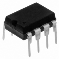
11AA080-I/P Microchip Technology, 11AA080-I/P Datasheet - Page 15

11AA080-I/P
Manufacturer Part Number
11AA080-I/P
Description
IC EEPROM 8KBIT 100KHZ 8DIP
Manufacturer
Microchip Technology
Datasheets
1.11LC010T-ITT.pdf
(44 pages)
2.11LC010T-ITT.pdf
(22 pages)
3.11LC010T-ITT.pdf
(6 pages)
4.11LC160T-ITT.pdf
(38 pages)
Specifications of 11AA080-I/P
Memory Size
8K (1K x 8)
Package / Case
8-DIP (0.300", 7.62mm)
Operating Temperature
-40°C ~ 85°C
Format - Memory
EEPROMs - Serial
Memory Type
EEPROM
Speed
100kHz
Interface
UNI/O™ (Single Wire)
Voltage - Supply
1.8 V ~ 5.5 V
Organization
1024 x 8
Interface Type
Serial
Maximum Clock Frequency
100 KHz
Supply Voltage (max)
5.5 V
Supply Voltage (min)
1.8 V
Maximum Operating Current
50 uA
Maximum Operating Temperature
+ 85 C
Mounting Style
Through Hole
Minimum Operating Temperature
- 40 C
Operating Supply Voltage
1.8 V
Lead Free Status / RoHS Status
Lead free / RoHS Compliant
Lead Free Status / RoHS Status
Lead free / RoHS Compliant, Lead free / RoHS Compliant
Available stocks
Company
Part Number
Manufacturer
Quantity
Price
Company:
Part Number:
11AA080-I/P
Manufacturer:
Microchip Technology
Quantity:
1 798
Company:
Part Number:
11AA080-I/P
Manufacturer:
MICROCHIP
Quantity:
12 000
Part Number:
11AA080-I/P
Manufacturer:
MIC
Quantity:
20 000
4.6
The
four levels of protection for the array by writing to the
appropriate bits in the STATUS register. The array is
divided up into four segments. The user has the ability
to write-protect none, one, two, or all four of the seg-
ments of the array. The partitioning is controlled as
illustrated in Table 4-3.
TABLE 4-3:
TABLE 4-4:
FIGURE 4-7:
2010 Microchip Technology Inc.
WRSR
Note 1: For the 11XXXX1, this bit must be a ‘1’.
SCIO
SCIO
BP1
0
0
1
1
Write Status Register (WRSR)
Instruction
Density
instruction allows the user to select one of
16K
1K
2K
4K
8K
0
ARRAY PROTECTION
PROTECTED ARRAY ADDRESS LOCATIONS
Standby Pulse
1
1
Command
WRITE STATUS REGISTER COMMAND SEQUENCE
BP0
0
0
1
0
1
1
1
1
0
180h-1FFh
300h-3FFh
600h-7FFh
Address Ranges Write-Protected
Upper 1/4
C0h-FFh
60h-7Fh
0
7 6 5 4
Start Header
Status Register Data
1
Preliminary
Upper 1/4
Upper 1/2
0
None
All
1
0
3 2 1 0
1
After transmitting the STATUS register data, the master
must transmit a NoMAK during the Acknowledge
sequence in order to initiate the internal write cycle.
Note: The
0
11AAXXX/11LCXXX
100h-1FFh
200h-3FFh
400h-7FFh
Upper 1/2
80h-FFh
1
40h-7Fh
nated with a NoMAK following the data
byte. If a NoMAK is not received at this
point, the command will be considered
invalid, and the device will go into Idle
mode without responding with a SAK or
executing the command.
Twc
WRSR
1
Address Ranges Unprotected
0
Device Address
1
instruction must be termi-
0
0
Lower 3/4
Lower 1/2
0
None
All
All Sectors
000h-1FFh
000h-3FFh
000h-7FFh
0
00h-FFh
00h-7Fh
DS22067H-page 15
0
(1)


