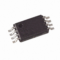
AT88SC0404CA-TH Atmel, AT88SC0404CA-TH Datasheet - Page 22

AT88SC0404CA-TH
Manufacturer Part Number
AT88SC0404CA-TH
Description
IC EEPROM 4KBIT 4MHZ 8TSSOP
Manufacturer
Atmel
Series
CryptoMemory®r
Datasheet
1.AT88SC0104CA-SU.pdf
(66 pages)
Specifications of AT88SC0404CA-TH
Format - Memory
EEPROMs - Serial
Memory Type
EEPROM
Memory Size
4K (512 x 8)
Speed
4MHz
Interface
I²C, 2-Wire Serial
Voltage - Supply
2.7 V ~ 3.6 V
Operating Temperature
-40°C ~ 85°C
Package / Case
8-TSSOP
Lead Free Status / RoHS Status
Lead free / RoHS Compliant
6.3.10. Password/Key Registers
6.3.11. Identification Number
6.3.12. Cryptograms (C
8664C–CRYPT–01/10
ER – Encryption Required
When ER = "0", the host is required to activate the encryption mode in order to read/write the corresponding user zone.
No data read from or written to the zone may be transmitted in the clear. If ER = "1", the host may activate the
encryption mode, but isn't specifically required to do so by the device.
WLM – Write Lock Mode
Asserting this bit (WLM = “0”) divides the user zone into 8-byte pages. The first byte of each page becomes the Write
Lock Byte and defines the locked/unlocked status for each byte in the page. Write access is forbidden to a byte if its
associated bit in the Write Lock Byte is set to “0”. Bit 7 controls byte 7; bit 6 controls byte 6, etc. By setting bit 0 to “0”
locks the Write Lock Byte itself. Enabling Write Lock Mode limits write operations to one byte at a time.
MDF – Modify Forbidden
Asserting this bit (MDF = “0”) renders the user zone read-only at all times. The user zone must, therefore, be
programmed before setting this bit to “0”
PGO – Program Only
Asserting this bit (PGO = “0”) allows changing of data within the user zone under protection from “1” to “0” and never
from “0” to “1”.
Four (Atmel
definition during device personalization. Each Password/Key register works in conjunction with a corresponding Access
register to define the security settings of each zone. The values programmed have an immediate effect on the logic of
the device. The default value is “1” for each bit. Bit 3 is reserved and should be left as value “1.”
Table 13. Password/Key Register Bit Map
AK(1:0) – Authentication Key
These bits define which of the four secret seeds G
zone if authentication is selected in the corresponding access register. Each access register may point to a unique
authentication secret, or access registers for multiple zones may point to the same authentication secret. In this case
authentication with a single secret seed will open several zones.
POK(1:0) – Program Only Key
When the user zone has the dual access mode selected (AM = "00"), these bits define which of the four secret seeds
G
PW(2:0) – Password Set
These bits define which of the eight password sets must be presented to allow access to the user zone when the
password mode is selected.
A 56-bit number the customer defines during personalization. It is recommended that a unique identification number be
assigned to each device.
Each of these fields contains a 56-bit cryptogram for use during authentication. The internal logic modifies the
cryptogram each time it successfully verifies the authentication. The customer may program an initial value for the
cryptogram during personalization. It is recommended that the initial values be random numbers.
0
-G
Bit 7
AK1
3
must be used in an authentication to allow read and program (i.e. write '0's only) access to the user zone.
®
AT88SC0104CA/0204CA/0404CA) or eight (Atmel AT88SC0808CA) 8-bit Password/Key registers receive
Bit 6
AK0
0
– C
3
)
POK1
Bit 5
Atmel AT88SC0104/0204/0404/0808/CA
POK0
Bit 4
0
-G
3
must be used in an authentication to allow access to the user
Bit 3
Res
Bit 2
PW2
Bit 1
PW1
Bit 0
PW0
21


