AT28C010-12UM/883 Atmel, AT28C010-12UM/883 Datasheet - Page 4
AT28C010-12UM/883
Manufacturer Part Number
AT28C010-12UM/883
Description
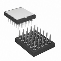
IC EEPROM 1MBIT 120NS 30PGA
Manufacturer
Atmel
Datasheet
1.AT28C010-15EM883.pdf
(17 pages)
Specifications of AT28C010-12UM/883
Format - Memory
EEPROMs - Parallel
Memory Type
EEPROM
Memory Size
1M (128K x 8)
Speed
120ns
Interface
Parallel
Voltage - Supply
4.5 V ~ 5.5 V
Operating Temperature
-55°C ~ 125°C
Package / Case
30-PGA
Lead Free Status / RoHS Status
Contains lead / RoHS non-compliant
Available stocks
Company
Part Number
Manufacturer
Quantity
Price


DC and AC Operating Range
Operating Modes
DC Characteristics
4
Operating
Temperature (Case)
V
Mode
Read
Write
Standby/Write Inhibit
Write Inhibit
Write Inhibit
Output Disable
Symbol
I
I
I
I
I
V
LI
LO
SB1
SB2
CC
CC
IL
Power Supply
(2)
AT28C010 Military
Parameter
Input Load Current
Output Leakage Current
V
V
V
Input Low Voltage
CC
CC
CC
Standby Current CMOS
Standby Current TTL
Active Current
Once set, SDP will remain active unless the disable command sequence is issued. Power transi-
tions do not disable SDP and SDP will protect the AT28C010 during power-up and power-down
conditions. All command sequences must conform to the page write timing specifications. The
data in the enable and disable command sequences is not written to the device and the memory
addresses used in the sequence may be written with data in either a byte or page write opera-
tion.
After setting SDP, any attempt to write to the device without the 3-byte command sequence will
start the internal write timers. No data will be written to the device; however, for the duration of
t
DEVICE IDENTIFICATION: An extra 128-bytes of EEPROM memory are available to the user
for device identification. By raising A9 to 12V ± 0.5V and using address locations 1FF80H to
1FFFFH the bytes may be written to or read from in the same manner as the regular memory
array.
OPTIONAL CHIP ERASE MODE: The entire device can be erased using a 6-byte software
code. Please see Software Chip Erase application note for details.
Notes:
WC
, read operations will effectively be polling operations.
Mil.
1. X can be VIL or VIH.
2. Refer to AC Programming Waveforms
Condition
V
V
CE = V
CE = 2.0V to V
f = 5 MHz; I
IN
I/O
AT28C010-12
-55°C - 125°C
= 0V to V
= 0V to V
5V ± 10%
CC
CE
V
V
V
X
X
X
IH
IL
IL
- 0.3V to V
OUT
CC
CC
CC
= 0 mA
+ 1V
+ 1V
CC
+ 1V
AT28C010-15
-55°C - 125°C
5V ± 10%
OE
V
V
V
V
X
X
IL
IH
IL
IH
(1)
AT28C010-20
-55°C - 125°C
Min
5V ± 10%
WE
V
V
V
X
X
X
IH
IL
IH
Max
300
0.8
10
10
80
3
I/O
D
D
High Z
High Z
AT28C010-25
-55°C - 125°C
OUT
IN
0010F–PEEPR–02/10
5V ± 10%
Units
mA
mA
μA
μA
μA
V
Related parts for AT28C010-12UM/883
Image
Part Number
Description
Manufacturer
Datasheet
Request
R

Part Number:
Description:
1 Megabit 128K x 8 Paged CMOS E2PROM
Manufacturer:
ATMEL [ATMEL Corporation]
Datasheet:
Part Number:
Description:
Space 1-megabit (128K x 8) Paged Parallel EEPROMs
Manufacturer:
ATMEL [ATMEL Corporation]
Datasheet:

Part Number:
Description:
Space 1-megabit 128k X 8 Paged Parallel Eeproms
Manufacturer:
ATMEL Corporation
Datasheet:
Part Number:
Description:
1-megabit 128k X 8 Paged Parallel Eeprom
Manufacturer:
ATMEL Corporation
Datasheet:
Part Number:
Description:
1 Megabit 128K x 8 Paged CMOS E2PROM
Manufacturer:
ATMEL Corporation
Datasheet:
Part Number:
Description:
1 Megabit 128K x 8 Paged CMOS E2PROM
Manufacturer:
ATMEL Corporation
Datasheet:

Part Number:
Description:
EEPROM 1M 5V SDP - 150NS
Manufacturer:
Atmel
Datasheet: