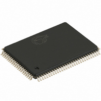
CY7C1347F-100AC Cypress Semiconductor Corp, CY7C1347F-100AC Datasheet

CY7C1347F-100AC
Specifications of CY7C1347F-100AC
Available stocks
Related parts for CY7C1347F-100AC
CY7C1347F-100AC Summary of contents
Page 1
... The CY7C1347F is a 3.3V, 128K by 36 synchronous-pipelined SRAM designed to support zero-wait-state secondary cache with minimal glue logic. CY7C1347F I/O pins can operate at either the 2.5V or the 3.3V level, the I/O pins are 3.3V tolerant when V All synchronous inputs pass through input registers controlled by the rising edge of the clock ...
Page 2
... D V DDQ V SSQ BYTE SSQ V DDQ DQP D Document #: 38-05213 Rev. *C -250 -225 -200 2.6 2.6 2.8 325 290 265 100-Pin TQFP CY7C1347F CY7C1347F -166 -133 -100 Unit 3.5 4.0 4.5 ns 240 225 205 DQP DDQ 76 V SSQ BYTE SSQ 70 V DDQ ...
Page 3
... Document #: 38-05213 Rev. *C 119-Ball BGA ADSP DDQ ADSC DQP DDQ ADV DDQ CLK BWE DDQ DQP MODE DDQ 165-Ball fBGA CLK CY7C1347F DDQ DQP DDQ DDQ DDQ DQP DDQ BWE ADSC ADV ADSP DDQ DDQ DDQ DDQ DDQ DDQ DDQ DDQ DDQ DDQ ...
Page 4
... Ground for the I/O circuitry. Selects Burst Order. When tied to GND selects linear burst sequence. When tied left floating selects interleaved burst sequence. This is a strap pin and DDQ should remain static during device operation. Mode Pin has an internal pull-up. No Connects. CY7C1347F , CE , and ...
Page 5
... Bytes not selected during a byte write operation will remain unaltered. A synchronous self-timed write mechanism has been provided to simplify the write operations. Because the CY7C1347F is a common I/O device, the Output Enable (OE) must be deasserted HIGH before presenting data to the DQs and DQPs inputs. Doing so will three-state the output drivers ...
Page 6
... and BWE = WRITE = H when all Byte write enable signals CY7C1347F Second Third Fourth Address Address Address [1:0] [1:0] [1: Min. Max CYC 2t CYC 2t CYC 0 OE CLK L-H three-state L-H three-state L-H three-state L-H three-state L-H three-state three-state L L-H three-state L L L-H three-state ...
Page 7
... Write Bytes Write All Bytes Write All Bytes Notes: 7. Table only lists a partial listing of the byte write combinations. Any combination of BW Document #: 38-05213 Rev ADSP ADSC ADV WRITE [ BWE valid. Appropriate write will be done based on which byte write is active. [A:D] CY7C1347F OE CLK L L ...
Page 8
... V V > V – 0.3V DDQ = 0 /2), undershoot: V (AC) > -2V (Pulse width less than t CYC IL (min.) within 200ms. During this time V < CY7C1347F Ambient Temperature V DD 0°C to +70°C 3.3V −5%/+10% –40°C to +85°C Min. Max. 3.135 3.6 2.375 V DD 2.4 2 ...
Page 9
... INCLUDING JIG AND (b) SCOPE R = 1667Ω 2.5V OUTPUT =1538Ω INCLUDING JIG AND SCOPE (b) Test Conditions Package Test conditions follow standard test methods and procedures for measuring thermal impedance, per EIA / JESD51. CY7C1347F Min. Max. 105 100 BGA fBGA Package Package ...
Page 10
... V POWER is less than t and t is less than t to eliminate bus contention between SRAMs when sharing the same OELZ CHZ CLZ = 3.3V and is 1.25V when V = 2.5V on all data sheets. DDQ CY7C1347F -200 -166 -133 1 1 6.0 7.5 2.5 3.0 3.5 2.5 3 ...
Page 11
... OEV OEHZ t OELZ t DOH Q(A2) Q( Q(A1) DON’T CARE UNDEFINED is HIGH and CE is LOW. When CE is HIGH, [A:D] CY7C1347F A3 Burst continued with new base address Deselect cycle t CHZ Q( Q( Q(A2) Q( Burst wraps around to its initial state BURST READ is HIGH LOW HIGH ...
Page 12
... BW[A:D] t CES t CEH CE ADV Data In (D) High-Z t CLZ Data Out (Q) Q(A1) High-Z Back-to-Back READs Document #: 38-05213 Rev WES t WEH OELZ D(A3) t OEHZ Q(A2) Single WRITE DON’T CARE UNDEFINED CY7C1347F A5 D(A5) Q(A4) Q(A4+1) Q(A4+2) Q(A4+3) BURST READ A6 D(A6) Back-to-Back WRITEs Page ...
Page 13
... The data bus (Q)remains in high-Z following a WRITE cycle, unless a new read access is initiated by ADSP or ADSC. 20 HIGH Document #: 38-05213 Rev WES t WEH OELZ D(A3) t OEHZ Q(A2) Single WRITE DON’T CARE UNDEFINED CY7C1347F A5 D(A5) Q(A4) Q(A4+1) Q(A4+2) Q(A4+3) BURST READ A6 D(A6) Back-to-Back WRITEs Page ...
Page 14
... Outputs (Q) Notes: 21. Device must be deselected when entering ZZ mode. See Cycle Descriptions table for all possible signal conditions to deselect the device. 22. DQs are in high-Z when exiting ZZ sleep mode. Document #: 38-05213 Rev RZZI DESELECT or READ Only High-Z DON’T CARE CY7C1347F t ZZREC Page ...
Page 15
... CY7C1347F-166BZC CY7C1347F-166AI CY7C1347F-166BGI 133 CY7C1347F-133AC CY7C1347F-133BGC CY7C1347F-133BZC CY7C1347F-133AI CY7C1347F-133BGI 100 CY7C1347F-100AC CY7C1347F-100BGC Shaded areas contain advance information. Please contact your local Cypress sales representative for availability of these parts. Document #: 38-05213 Rev. *C Package Name Package Type A101 100-Lead Thin Quad Flat Pack ...
Page 16
... Package Diagrams 100-Pin Thin Plastic Quad Flatpack ( 1.4 mm) A101 Document #: 38-05213 Rev. *C CY7C1347F 51-85050-*A Page ...
Page 17
... Package Diagrams (continued) Document #: 38-05213 Rev. *C 119-Lead PBGA ( 2.4 mm) BG119 CY7C1347F 51-85115-*B Page ...
Page 18
... The inclusion of Cypress Semiconductor products in life-support systems application implies that the manufacturer assumes all risk of such use and in doing so indemnifies Cypress Semiconductor against all charges. 165-Ball FBGA ( 1.20 mm) BB165C CY7C1347F PIN 1 CORNER BOTTOM VIEW Ø0. Ø0. Ø0.45±0.05(165X) 11 ...
Page 19
... Document History Page Document Title: CY7C1347F 4-Mb (128K x 36) Pipelined Sync SRAM Document Number: 38-05213 REV. ECN NO. Issue Date ** 119829 12/16/02 *A 123117 01/18/03 *B 127632 06/13/03 *C 200660 See ECN Document #: 38-05213 Rev. *C Orig. of Change Description of Change HGK New Data Sheet RBI Added power-up requirements to AC test loads and waveforms information ...


