DS1218 Maxim Integrated Products, DS1218 Datasheet
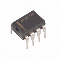
IC CONTROLLER NV 8-DIP

DS1218

Manufacturer Part Number
DS1218
Description
IC CONTROLLER NV 8-DIP
Manufacturer
Maxim Integrated Products
Datasheet

Specifications of DS1218

Controller Type
Nonvolatile RAM
Voltage - Supply
4.5 V ~ 5.5 V
Operating Temperature
0°C ~ 70°C
Package / Case
8-DIP (0.300", 7.62mm)
Lead Free Status / RoHS Status
Contains lead / RoHS non-compliant

Available stocks

Company
Part Number
Manufacturer
Quantity
Price
Part Number:
DS1218
Quantity:
5 510
Part Number:
DS1218
Manufacturer:
DALLAS
Quantity:
1
Part Number:
DS1218
Manufacturer:
DALLAS
Quantity:
20 000
Company:
Part Number:
DS1218
Quantity:
50
Part Number:
DS1218+
Manufacturer:
TI
Quantity:
1 945
Part Number:
DS1218+
Manufacturer:
Maxim Integrated Products
Quantity:
135
Part Number:
DS121882
Quantity:
5 510
Part Number:
DS121882
Quantity:
5 510
Part Number:
DS1218S+TR
Manufacturer:
MAXIM/美信
Quantity:
20 000
FEATURES
DESCRIPTION
The DS1218 is a CMOS circuit which solves the application problems of converting CMOS RAM into
nonvolatile memory. Incoming power is monitored for an out-of-tolerance condition. When such a
condition is detected, the chip enable output is inhibited to accomplish write protection and the battery is
switched on to supply RAM with uninterrupted power. Special circuitry uses a low-leakage CMOS
process which affords precise voltage detection at extremely low battery consumption. The 8-pin mini-
DIP package keeps PC board real estate requirements to a minimum. By combining the DS1218
nonvolatile controller chip with a full CMOS memory and lithium batteries, 10 years of nonvolatile RAM
operation can be achieved.
OPERATION
The DS1218 Nonvolatile Controller performs the circuit functions required to battery back-up a RAM.
First, a switch is provided to direct power from the battery or V
This switch has a voltage drop of less than 0.2V. The second function which the nonvolatile controller
provides is power-fail detection. The DS1218 constantly monitors the V
1.26 times the battery voltage, a precision comparator outputs a power-fail detect signal to the chip enable
logic. The third function of write protection is accomplished by holding the chip enable output signal to
within 0.2V of the V
During nominal supply conditions, the chip enable output will follow chip enable input with a maximum
propagation delay of 10 ns.
www.dalsemi.com
Converts CMOS RAM into nonvolatile
memories
Unconditionally write protects when V
out of tolerance
Automatically switches to battery when
power fail occurs
Space saving 8-pin mini-DIP/8-pin 150 mil
SOIC
Consumes less than 100 na of battery current
CCI
or battery supply, when a power-fail condition is detected.
CC
is
1 of 4
PIN ASSIGNMENT
PIN DESCRIPTION
V
V
NC
V
GND
CEI
CEO
CCI
CCO
BAT
GND
V
CCO
NC
NC
CCI
3
1
2
4
Nonvolatile Controller
supply, depending on which is greater.
- Input +5 Volt Supply
- RAM Power (V
- Chip Enable Input
- No Connection
- Chip Enable Output
- + Battery
- Ground
CC
8
7
6
5
supply. When V
V
V
CEO
CEI
CCI
BAT
CC
) Supply
DS1218
CCI
111899
falls to

Related parts for DS1218

DS1218 Summary of contents

Page 1

... Consumes less than 100 na of battery current DESCRIPTION The DS1218 is a CMOS circuit which solves the application problems of converting CMOS RAM into nonvolatile memory. Incoming power is monitored for an out-of-tolerance condition. When such a condition is detected, the chip enable output is inhibited to accomplish write protection and the battery is switched on to supply RAM with uninterrupted power ...

Page 2

... IN C OUT ( SYMBOL MIN TYP 0.2 REC t 500 MAX UNITS 5.5 V 5.5 V 0 ± 10%) CCI MAX UNITS 5 mA 100 +1.0 µA mA 4.0 mA BAT (t = 25°C) A MAX UNITS 5.0V ± 10%) CC MAX UNITS µs 1.5 µs DS1218 NOTES NOTES NOTES NOTES ...

Page 3

... TIMING DIAGRAM: POWER-UP TIMING DIAGRAM: POWER-DOWN DS1218 ...

Page 4

... Outputs open. 4. Drain from battery when V 5. Maximum amount of current which can be drawn through pin 1 of the controller max must be met to ensure data integrity on power loss can only sustain leakage current in the battery backup mode. CEO OUTPUT LOAD Figure 1 < BAT DS1218 ...

Related keywords