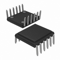
TOP264VG Power Integrations, TOP264VG Datasheet - Page 36

TOP264VG
Manufacturer Part Number
TOP264VG
Description
IC OFFLINE SW PWM OCP OVP 12EDIP
Manufacturer
Power Integrations
Series
TOPSwitch®-JXr
Type
Off Line Switcherr
Datasheet
1.TOP264EG.pdf
(40 pages)
Specifications of TOP264VG
Output Isolation
Isolated
Frequency Range
66 ~ 132kHz
Voltage - Output
725V
Power (watts)
22.5W
Operating Temperature
-40°C ~ 150°C
Package / Case
12-SDIP (0.412", 10.46mm) Exposed Pad
Output Voltage
12 V
Switching Frequency
132 KHz, 66 KHz
Supply Current
2.9 mA, 3.1 mA
Operating Temperature Range
- 40 C to + 150 C
Mounting Style
Through Hole
Maximum Operating Temperature
+ 150 C
Minimum Operating Temperature
- 40 C
Output Power
12 W, 22.5 W
Lead Free Status / RoHS Status
Lead free / RoHS Compliant
Other names
596-1269-5
Available stocks
Company
Part Number
Manufacturer
Quantity
Price
Company:
Part Number:
TOP264VG
Manufacturer:
PowerInt
Quantity:
2 267
Part Number:
TOP264VG
Manufacturer:
POWER
Quantity:
20 000
Rev. C 11/10
36
(Laser Marked)
0.004 [0.10] C B
Pin #1 I.D.
0.031 [0.80]
0.028 [0.72]
0.019 [0.48]
0.350 [8.89]
0.07 [1.78]
2X
B
Ref.
H
TOP264-271
2
12 11 10 9 8
1 2 3 4
TOP VIEW
0.316 [8.03]
0.356 [9.04]
SIDE VIEW
0.03 [0.76]
Ref.
Ref.
0.070 [1.78]
5
6
7
0.213 [5.41]
0.400 [10.16]
Ref.
0.192 [4.87]
0.049 [1.23]
0.046 [1.16]
Mounting
Hole Pattern
Dimensions
Ref.
0.412 [10.46]
eDIP-12 (V Package)
Drill Hole
Round Pad
Solder Mask 0.056 [1.42]
Ref.
0.010 [0.25] Ref.
Seating Plane
0.022 [0.56]
0.020 [0.51]
0.104 [2.65] Ref.
0.306 [7.77]
DETAIL A (Not drawn to scale)
Detail A
Ref.
Ref.
0.092 [2.34]
0.086 [2.18]
Ref.
0.03 [0.76]
0.05 [1.27]
END VIEW
C
0.016 [0.41]
0.011 [0.28]
0.028 [0.71]
0.400 [10.16]
5 ±
°
Ref.
4
°
0.436 [11.08]
0.406 [10.32]
0.004 [0.10] C A
7
12×
Notes:
1. Dimensioning and tolerancing per
2. Dimensions noted are determined
3. Dimensions noted are inclusive of plating
4. Does not include inter-lead flash or
5. Controlling dimensions in inches [mm].
6. Datums A & B to be determined at Datum H.
7. Measured with the leads constrained to be
8. Measured with the leads unconstrained.
9. Lead numbering per JEDEC SPP-012.
ASME Y14.5M-1994.
at the outermost extremes of the plastic
body exclusive of mold flash, tie bar
burrs, gate burrs, and interlead flash,
but including any mismatch between the
top and bottom of the plastic body. Maximum
mold protrusion is 0.007 [0.18] per side.
thickness.
protrusions.
perpendicular to Datum C.
8
6
7
0.400 [10.16]
BOTTOM VIEW
0.023 [0.58]
0.018 [0.46]
0.010 [0.25] M C A B
2
12
1
www.powerint.com
(Laser Marked)
12×
A
0.059 [1.50]
0.059 [1.50]
Pin #1 I.D.
3
Ref, typ.
PI-5556-110210
Ref, typ.
4


