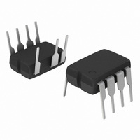
NCP1217P65G ON Semiconductor, NCP1217P65G Datasheet - Page 14

NCP1217P65G
Manufacturer Part Number
NCP1217P65G
Description
IC CTRLR PWM CM OVP HV 8DIP
Manufacturer
ON Semiconductor
Datasheet
1.NCP1217P100G.pdf
(19 pages)
Specifications of NCP1217P65G
Output Isolation
Isolated
Frequency Range
58.5 ~ 71.5kHz
Voltage - Input
10 ~ 16 V
Operating Temperature
0°C ~ 150°C
Package / Case
8-DIP (0.300", 7.62mm), 7 Leads
Number Of Outputs
1
Duty Cycle (max)
74 % (Typ)
Output Current
500 mA
Mounting Style
Through Hole
Switching Frequency
65 KHz (Typ)
Operating Supply Voltage
16 V
Maximum Operating Temperature
+ 150 C
Fall Time
20 ns
Rise Time
60 ns
Synchronous Pin
No
Topology
Flyback
Lead Free Status / RoHS Status
Lead free / RoHS Compliant
Other names
NCP1217P65GOS
Protecting the Controller Against Negative Spikes
is the designer’s duty to avoid the presence of negative
spikes on sensitive pins. Negative signals have the bad habit
to forward bias the controller substrate and induce erratic
behaviors. Sometimes, the injection can be so strong that
As with any controller built upon a CMOS technology, it
Figure 26. Another Way of Shutting Down the IC
Without a Definitive Latchoff State
ON/OFF
Q1
1
2
3
4
http://onsemi.com
8
7
6
5
14
internal parasitic SCRs are triggered, engendering
irremediable damages to the IC if a low impedance path is
offered between V
often the seat of such spurious signals, the high- -voltage pin
can also be the source of problems in certain circumstances.
During the turn- -off sequence, e.g. when the user unplugs the
power supply, the controller is still fed by its V
and keeps activating the MOSFET ON and OFF with a peak
current limited by Rsense. Unfortunately, if the quality
coefficient Q of the resonating network formed by Lp and
Cbulk is low (e.g. the MOSFET Rdson + Rsense are small),
conditions are met to make the circuit resonate and thus
negatively bias the controller. Since we are talking about ms
pulses, the amount of injected charge (Q = I * t) immediately
latches the controller that brutally discharges its V
capacitor. If this V
stored energy damages the controller. Figure 27 depicts a
typical negative shot occurring on the HV pin where the
brutal V
CC
discharge testifies for latchup.
CC
CC
and GND. If the current sense pin is
capacitor is of sufficient value, its
CC
capacitor
CC


