LTC1998CS6#TR Linear Technology, LTC1998CS6#TR Datasheet - Page 10

LTC1998CS6#TR
Manufacturer Part Number
LTC1998CS6#TR
Description
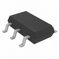
IC COMP/PREC ADJ REF TSOT23-6
Manufacturer
Linear Technology
Datasheet
1.LTC1998CS6TRMPBF.pdf
(12 pages)
Specifications of LTC1998CS6#TR
Function
Over/Under Voltage Protection
Battery Type
Lithium-Ion (Li-Ion)
Voltage - Supply
1 V ~ 5.5 V
Operating Temperature
-40°C ~ 85°C
Mounting Type
Surface Mount
Package / Case
SOT-23-6 Thin, TSOT-23-6
Lead Free Status / RoHS Status
Contains lead / RoHS non-compliant
Other names
LTC1998CS6TR
Available stocks
Company
Part Number
Manufacturer
Quantity
Price
LTC1998
APPLICATIONS INFORMATION
The calculation of the resistor values R1, R2 and R3 is
quite straightforward and similar to the procedure outlined
in the previous paragraph.
Choose a value for the sum of R1 + R2 + R3 as well as the
values for low battery threshold and hysteresis.
Solve for resistor R1:
Solve for the sum of
then solve for R2 and R3.
Example: A system needs to detect a low battery
voltage of 3V (V
(V
(R1 + R2 + R3) = 1M.
R1 = 539k, R1 + R2 = 667k, R2 = 128k, R3 = 333k.
Choose the closest 1% values, that is 536k, 332k, 127k.
Figure 4 graphically shows the function of the LTC1998 as
described above.
10
(
R
TH2
1
R
+
1
R
=
= 3.25V). Set the value of the resistor divider
2
(
) (
R
=
1
+
R
R
1
+
2
R
+
BATT.Th
2
R
+
3
)
R
⎛
⎝ ⎜
3
V
)
= 3V) with 250mV hysteresis
5
TH
⎛
⎝ ⎜
V
V
2
BATT Th
–
5
1
V
⎞
⎠ ⎟
.
–
1
⎞
⎠ ⎟
PROGRAMMED
PROGRAMMED
VERSATILE OUTPUT DRIVER
V
The LTC1998 uses a CMOS push-pull output stage to drive
the low battery output signal. This output pin (BATTLO)
has a separate supply pin, (V
provide an output voltage rail matching the V
microprocessors. The V
age lower than the voltage at the BATT pin. The V
pin may also be tied to a voltage higher than V
series resistor greater than 10k. The output will then act
as an open-drain device.
In a given application, if it is possible for BATTLO to be
shorted to GND or a supply, a series resistor should be
added to limit the short-circuit current to 5mA.
LOGIC
HYSTERESIS
THRESHOLD
THRESHOLD
LOW BATT
BATTLO
V
3.25V
2.50V
LOGIC
, BATTLO (Pins 5,6)
Figure 4. LTC1998 Function Plot
THRESHOLD RANGE
PROGRAMMABLE
BATTERY
VOLTAGE
LOGIC
LOGIC
pin may be tied to a volt-
) that can be used to
HYSTERESIS
BATTERY VOLTAGE
RECOVERS UNDER
REDUCED LOAD
DD
BATT
logic of
LOGIC
via a
1998fb
1998 F04


