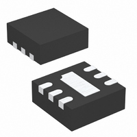
LTC4065LEDC#TRMPBF Linear Technology, LTC4065LEDC#TRMPBF Datasheet - Page 12

LTC4065LEDC#TRMPBF
Manufacturer Part Number
LTC4065LEDC#TRMPBF
Description
IC CHARGER LI-ION 6-DFN
Manufacturer
Linear Technology
Datasheet
1.LTC4065LXEDCTRPBF.pdf
(16 pages)
Specifications of LTC4065LEDC#TRMPBF
Function
Charge Management
Battery Type
Lithium-Ion (Li-Ion)
Voltage - Supply
3.75 V ~ 5.5 V
Operating Temperature
-40°C ~ 85°C
Mounting Type
Surface Mount
Package / Case
6-WFDFN Exposed Pad
Lead Free Status / RoHS Status
Lead free / RoHS Compliant
Available stocks
Company
Part Number
Manufacturer
Quantity
Price
APPLICATIO S I FOR ATIO
Undervoltage Charge Current Limiting (UVCL)
The LTC4065L includes undervoltage charge (∆V
current limiting that prevents full charge current until the
input supply voltage reaches approximately 200mV above
the battery voltage. This feature is particularly useful if the
LTC4065L is powered from a supply with long leads (or
any relatively high output impedance).
For example, USB-powered systems tend to have highly
variable source impedances (due primarily to cable quality
and length). A transient load combined with such imped-
ance can easily trip the UVLO threshold and turn the
charger off unless undervoltage charge current limiting is
implemented.
Consider a situation where the LTC4065L is operating
under normal conditions and the input supply voltage
begins to droop (e.g., an external load drags the input
supply down). If the input voltage reaches V
(approximately 220mV above the battery voltage),
undervoltage charge current limiting will begin to reduce
the charge current in an attempt to maintain ∆V
between the V
LTC4065L will continue to operate at the reduced charge
current until the input supply voltage is increased or
voltage mode reduces the charge current further.
LTC4065L/LTC4065LX
12
CC
input and the BAT output of the IC. The
U
U
ADAPTER
W
5V WALL
POWER
Figure 3. Combining Wall Adapter and USB Power
USB
BAT
MP1
U
+ ∆V
UVCL1
1k
UVCL1
UVCL1
D1
4
)
V
LTC4065L
CC
USB and Wall Adapter Power
Although the LTC4065L allows charging from a USB port,
a wall adapter can also be used to charge Li-Ion batteries.
Figure 3 shows an example of how to combine wall adapter
and USB power inputs. A P-channel MOSFET, MP1, is
used to prevent back conducting into the USB port when
a wall adapter is present and Schottky diode, D1, is used
to prevent USB power loss through the 1k pull-down
resistor.
Stability Considerations
The LTC4065L contains two control loops: constant-
voltage and constant-current. The constant-voltage loop
is stable without any compensation when a battery is
connected with low impedance leads. Excessive lead
length, however, may add enough series inductance to
require a bypass capacitor of at least 1µF from BAT to
GND. Furthermore, a 4.7µF capacitor with a 0.2Ω to 1Ω
series resistor from BAT to GND is required to keep ripple
voltage low when the battery is disconnected.
High value capacitors with very low ESR (especially ce-
ramic) may reduce the constant-voltage loop phase mar-
gin. Ceramic capacitors up to 22µF may be used in parallel
with a battery, but larger ceramics should be decoupled
with 0.2Ω to 1Ω of series resistance.
PROG
BAT
3
6
I
800Ω
BAT
+
4065L F03
Li-Ion
BATTERY
SYSTEM
LOAD
4065lxfa


