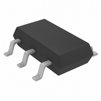
LTC1734ES6-4.1#TRMPBF Linear Technology, LTC1734ES6-4.1#TRMPBF Datasheet - Page 5

LTC1734ES6-4.1#TRMPBF
Manufacturer Part Number
LTC1734ES6-4.1#TRMPBF
Description
IC BATT CHRGR LI-ION LIN SOT23-6
Manufacturer
Linear Technology
Datasheet
1.LTC1734ES6-4.2TRMPBF.pdf
(12 pages)
Specifications of LTC1734ES6-4.1#TRMPBF
Function
Charge Management
Battery Type
Li-Ion, NiCd, NiMH
Voltage - Supply
4.55 V ~ 8 V
Operating Temperature
-40°C ~ 85°C
Mounting Type
Surface Mount
Package / Case
SOT-23-6 Thin, TSOT-23-6
Lead Free Status / RoHS Status
Lead free / RoHS Compliant
Other names
LTC1734ES6-4.1#PBF
LTC1734ES6-4.1#PBF
LTC1734ES6-4.1#PBF
Available stocks
Company
Part Number
Manufacturer
Quantity
Price
PIN
I
from V
tor and reappears at I
external PNP emitter. The PNP collector provides charge
current to the battery.
GND (Pin 2): Ground. Provides a reference for the internal
voltage regulator and a return for all internal circuits.
When in the constant voltage mode, the LTC1734 will
precisely regulate the voltage between the BAT and GND
pins. The battery ground should connect close to the GND
pin to avoid voltage drop errors.
V
supplies power to the internal control circuitry and exter-
nal PNP transistor through the internal current sense
resistor. This pin should be bypassed to ground with a
capacitor in the range of 1 F to 10 F.
PROG (Pin 4): Charge Current Programming, Charge
Current Monitor and Manual Shutdown Pin. Provides a
virtual reference voltage of 1.5V for an external resistor
(R
the battery charge current when the charger is in the
constant current mode. The typical charge current will be
1000 times greater than the current through this resistor
BLOCK DIAGRA
SENSE
CC
PROG
U
(Pin 3): Positive Input Supply Voltage. This pin
FUNCTIONS
CC
(Pin 1): Sense Node for Charge Current. Current
) tied between this pin and ground that programs
passes through the internal current sense resis-
U
2.15V
U
+
–
REFERENCE
VOLTAGE
SENSE
UVLO
2.5V
W
C1
to supply current to the
REF
SHUTDOWN
SHUTDOWN
I
BAT
/1000
3 A
1 F
4
60
1.5V
R
PROG
PROG
–
V
A3
3
IN
+
–
V
CC
+
A2
I
BAT
0.06
(I
current to be monitored. The voltage on this pin is propor-
tional to the charge current where 1.5V corresponds to the
full programmed currrent. Floating this pin allows an
internal current source to pull the pin voltage above the
shutdown threshold voltage. Because this pin is in a signal
path, excessive capacitive loading can cause AC instabil-
ity. See the Applications Information section for more
details.
BAT (Pin 5): Battery Voltage Sense Input. A precision
internal resistor divider sets the final float voltage on this
pin. This divider is disconnected in the manual shutdown
or sleep mode. When charging, approximately 34 A
flows into the BAT pin. To minimize float voltage errors,
avoid excessive resistance between the battery and the
BAT pin. For dynamically stable operation, this pin usually
requires a minimum bypass capacitance to ground of 5 F
to frequency compensate for the high frequency inductive
effects of the battery and wiring.
DRIVE (Pin 6): Base Drive Output for the External PNP
Pass Transistor. Provides a controlled sink current that
drives the base of the PNP. This pin has current limiting
protection for the LTC1734.
BAT
TEMPERATURE AND
CURRENT LIMITING
= 1500/R
SHUTDOWN
OUTPUT
DRIVER
A1
SHUTDOWN
+
–
PROG
2.5V
). This pin also allows for the charge
2
GND
1
6
5
1734 BD
I
DRIVE
BAT
SENSE
10 F
I
BAT
SINGLE
Li-Ion
CELL
LTC1734
5


