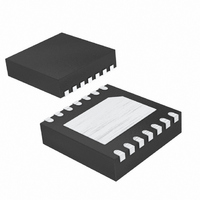
MAX8606ETD+T Maxim Integrated Products, MAX8606ETD+T Datasheet - Page 6

MAX8606ETD+T
Manufacturer Part Number
MAX8606ETD+T
Description
IC CHARGER LI+ W/SW 14TDFN
Manufacturer
Maxim Integrated Products
Datasheet
1.MAX8606ETDT.pdf
(14 pages)
Specifications of MAX8606ETD+T
Function
Charge Management
Battery Type
Lithium-Ion (Li-Ion)
Voltage - Supply
4.25 V ~ 5.5 V
Operating Temperature
-40°C ~ 85°C
Mounting Type
Surface Mount
Package / Case
14-WFDFN Exposed Pad
Product
Charge Management
Output Voltage
3.3 V
Operating Supply Voltage
6 V to 14 V
Supply Current
1.2 mA
Maximum Operating Temperature
+ 85 C
Minimum Operating Temperature
- 40 C
Charge Safety Timers
Yes
Mounting Style
SMD/SMT
Temperature Monitoring
Yes
Uvlo Start Threshold
4 V
Uvlo Stop Threshold
3.5 V
Lead Free Status / RoHS Status
Lead free / RoHS Compliant
The MAX8606 charger uses current, voltage, and ther-
mal control loops to charge and protect a single Li+
battery cell. It can start the system even when the bat-
tery is in deep saturation. The MAX8606 provides a
SYS output that supplies the external system with a
minimum 3.5V at 1A.
Two active-low enable inputs (EN1 and EN2) are sup-
plied to set the SYS and charging current limits. During
prequal and fast-charge modes, the CHG output status
flag is pulled low. As the battery voltage approaches
USB/AC Adapter, Li+ Linear Battery Charger
with Integrated 50m Ω Battery Switch in TDFN
6
_______________________________________________________________________________________
13, 14
PIN
1, 2
10
11
12
—
3
4
5
6
7
8
9
NAME
CHG
GND
THM
POK
TMR
SETI
BAT
EN2
EN1
SYS
VL
EP
IN
Detailed Description
Batter y C onnecti on. The IC d el i ver s char g i ng cur r ent and m oni tor s b atter y vol tag e usi ng BAT. C onnect
b oth BAT outp uts tog ether exter nal l y. D ur i ng susp end m od e, BAT i s i nter nal l y connected to S Y S .
Supply Voltage Input. Connect IN to a 4.25V to 5.5V supply. Charging is suspended if V
6V. Bypass IN to GND with a 4.7µF or larger ceramic capacitor.
+3.3V Output Voltage and Logic Supply. VL is regulated to +3.3V and is capable of sourcing 500µA
to provide power for external circuits. Bypass VL to GND with a 0.1µF or larger ceramic capacitor. VL
is internally pulled to GND during suspend mode.
Thermistor Input. Connect a 10kΩ NTC thermistor from THM to GND in close proximity to the battery
to monitor the battery temperature. The IC suspends charging when the temperature is outside the
hot and cold limits. Connect THM to GND to disable the thermistor monitoring function.
Charging Status Output. CHG is an open-drain output that goes low when the battery is charging.
CHG goes high impedance when the charge current drops below 50mA (typ) and the battery voltage
is 4.2V (typ). CHG is high impedance when the IC is in suspend mode.
P ower - OK M oni tor . P O K i s an op en- d r ai n outp ut that pul l s l ow w hen a val id char g ing sour ce i s d etected at IN .
Timer-Selection Input. Drive TMR high to enable the microprocessor mode where the charge times
are determined by an external device. Drive TMR low to use the internal prequal, fast-charge, and
top-off timers.
Charge-Current Selection Input. Drive EN_ high or low to select the charge current or to put the
MAX8606 into suspend mode (see Table 1).
Charge-Current Selection Input. Drive EN_ high or low to select the charge current or to put the
MAX8606 into suspend mode (see Table 1).
Ground. Connect directly to exposed paddle under the IC.
Charge-Current Programming Input. Connect a resistor from SETI to GND to set the maximum
charging current. R
System Supply Output. SYS delivers up to 1A
with a 4.7µF or larger ceramic capacitor. SYS is connected to BAT through an internal 50mΩ switch
when V
Exposed Paddle. Connect to GND under the IC. Connect to a large ground plane to improve power
dissipation.
BAT
exceeds 3.5V or when the MAX8606 is in suspend mode.
SETI
must be between 17.68kΩ and 35.36kΩ.
4.2V, the charging current is reduced. When the charg-
ing current drops below 50mA and the battery voltage
equals 4.2V, the CHG output goes high impedance,
signaling a full battery. At any time during charging, if
both EN1 and EN2 are driven high, the charger enters
suspend mode, charging stops, and CHG goes high
impedance.
The MAX8606 contains an internal timer to measure the
prequal, fast-charge, and top-off charge time. If the
battery voltage has not risen above 3V after 30 minutes
or has not completed fast-charge in 8 hours, the charg-
er goes into a fault state where the charging is
RMS
FUNCTION
to power an external system. Bypass SYS to GND
Pin Description
IN
exceeds


