DS2777G+T&R Maxim Integrated Products, DS2777G+T&R Datasheet - Page 40
DS2777G+T&R
Manufacturer Part Number
DS2777G+T&R
Description
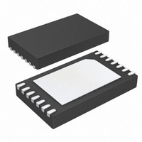
IC FUEL GAUGE LI+ 2CELL 14-TDFN
Manufacturer
Maxim Integrated Products
Datasheet
1.DS2775G.pdf
(46 pages)
Specifications of DS2777G+T&R
Function
Fuel, Gas Gauge/Monitor
Battery Type
Lithium-Ion (Li-Ion), Lithium-Polymer (Li-Pol)
Voltage - Supply
4 V ~ 9.2 V
Operating Temperature
-20°C ~ 70°C
Mounting Type
Surface Mount
Package / Case
14-TDFN
Lead Free Status / RoHS Status
Lead free / RoHS Compliant


2-Cell, Stand-Alone, Li+ Fuel-Gauge IC with
Protector and Optional SHA-1 Authentication
Figure 28. Clear/Lock Secret, Set/Clear Overdrive Commands
Figure 29. 1-Wire Initialization Sequence
The 1-Wire bus requires strict signaling protocols to
ensure data integrity. The four protocols used by the
DS2775/DS2776 are as follows: the initialization
sequence (reset pulse followed by presence pulse),
write-zero, write-one, and read data. The bus master
initiates all these types of signaling except the pres-
ence pulse.
40
______________________________________________________________________________________
DQ
1-Wire
RESET
PRESENCE
PULSE
COMMAND
SKIP-ROM
LINE TYPE LEGEND:
1-Wire Signaling
BUS MASTER ACTIVE LOW
RESISTOR PULLUP
t
RSTL
OVERDRIVE COMMAND
t
PDH
SECRET COMMAND
OR SET/CLEAR
CLEAR/LOCK
Figure 29 shows the initialization sequence required to
begin any communication with the DS2775/DS2776. A
presence pulse following a reset pulse indicates that
the DS2775/DS2776 are ready to accept a Net Address
command. The bus master transmits (Tx) a reset pulse
for t
goes into receive mode (Rx). The 1-Wire bus line is
then pulled high by the pullup resistor. After detecting
the rising edge on the DQ pin, the DS2775/DS2776 wait
for t
PDH
RSTL
t
DS2775/DS2776 ACTIVE LOW
PDL
and then transmit the presence pulse for t
. The bus master then releases the line and
t
RSTH
WAIT FOR EEPROM
t
EEC
COPY TIME
PK+
PK-
PDL
.
Related parts for DS2777G+T&R
Image
Part Number
Description
Manufacturer
Datasheet
Request
R

Part Number:
Description:
IC FUEL GAUGE LI+ 2CELL 14-TDFN
Manufacturer:
Maxim Integrated Products
Datasheet:

Part Number:
Description:
2-Cell, Stand-Alone, Li+ Fuel-Gauge IC with Protector and Optional SHA-1 Authentication
Manufacturer:
MAXIM [Maxim Integrated Products]
Datasheet:

Part Number:
Description:
MAX7528KCWPMaxim Integrated Products [CMOS Dual 8-Bit Buffered Multiplying DACs]
Manufacturer:
Maxim Integrated Products
Datasheet:
Part Number:
Description:
Single +5V, fully integrated, 1.25Gbps laser diode driver.
Manufacturer:
Maxim Integrated Products
Datasheet:
Part Number:
Description:
Single +5V, fully integrated, 155Mbps laser diode driver.
Manufacturer:
Maxim Integrated Products
Datasheet:
Part Number:
Description:
VRD11/VRD10, K8 Rev F 2/3/4-Phase PWM Controllers with Integrated Dual MOSFET Drivers
Manufacturer:
Maxim Integrated Products
Datasheet:
Part Number:
Description:
Highly Integrated Level 2 SMBus Battery Chargers
Manufacturer:
Maxim Integrated Products
Datasheet:
Part Number:
Description:
Current Monitor and Accumulator with Integrated Sense Resistor; ; Temperature Range: -40°C to +85°C
Manufacturer:
Maxim Integrated Products
Part Number:
Description:
TSSOP 14/A°/RS-485 Transceivers with Integrated 100O/120O Termination Resis
Manufacturer:
Maxim Integrated Products
Part Number:
Description:
TSSOP 14/A°/RS-485 Transceivers with Integrated 100O/120O Termination Resis
Manufacturer:
Maxim Integrated Products
Part Number:
Description:
QFN 16/A°/AC-DC and DC-DC Peak-Current-Mode Converters with Integrated Step
Manufacturer:
Maxim Integrated Products
Part Number:
Description:
TDFN/A/65V, 1A, 600KHZ, SYNCHRONOUS STEP-DOWN REGULATOR WITH INTEGRATED SWI
Manufacturer:
Maxim Integrated Products
Part Number:
Description:
Integrated Temperature Controller f
Manufacturer:
Maxim Integrated Products
Part Number:
Description:
SOT23-6/I°/45MHz to 650MHz, Integrated IF VCOs with Differential Output
Manufacturer:
Maxim Integrated Products
Part Number:
Description:
SOT23-6/I°/45MHz to 650MHz, Integrated IF VCOs with Differential Output
Manufacturer:
Maxim Integrated Products