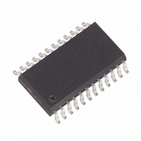
MAX7221CWG+ Maxim Integrated Products, MAX7221CWG+ Datasheet - Page 11

MAX7221CWG+
Manufacturer Part Number
MAX7221CWG+
Description
IC DRIVER LED DISP 8DGT 24-SOIC
Manufacturer
Maxim Integrated Products
Datasheet
1.MAX7221CWG.pdf
(16 pages)
Specifications of MAX7221CWG+
Display Type
LED
Configuration
7 Segment + DP
Interface
4-Wire Serial
Digits Or Characters
8 Digits
Current - Supply
330mA
Voltage - Supply
4 V ~ 5.5 V
Operating Temperature
0°C ~ 70°C
Mounting Type
Surface Mount
Package / Case
24-SOIC (7.5mm Width)
Number Of Digits
8
Number Of Segments
7
Low Level Output Current
320000 uA (Min)
High Level Output Current
65 mA
Operating Supply Voltage
4 V to 5.5 V
Maximum Supply Current
330 mA
Maximum Power Dissipation
941 mW
Maximum Operating Temperature
+ 70 C
Mounting Style
SMD/SMT
Minimum Operating Temperature
0 C
Lead Free Status / RoHS Status
Lead free / RoHS Compliant
Table 11. R
LED Forward Voltage
The upper limit for power dissipation (PD) for the
MAX7219/MAX7221 is determined from the following
equation:
where:
Dissipation example:
Thus, for a CERDIP package (θ
Table 12), the maximum allowed ambient temperature
T
where T
The T
example above are +66.7°C and +55.6°C, respectively.
A
I
SEG
PD = (V+ x 8mA) + (V+ - V
V+ = supply voltage
DUTY = duty cycle set by intensity register
N = number of segments driven (worst case is 8)
V
I
I
40mA, V+ = 5.25V
PD = (5.25V x 8mA) + (5.25V - 1.8V)(31/32 x
40mA x 8) = 1.11W
Serially Interfaced, 8-Digit LED Display Drivers
T
150°C = T
is given by:
SEG
SEG
LED
J(MAX)
40
30
20
10
A
(mA)
limits for PDIP and SO packages in the dissipation
A
= segment current set by R
= 40mA, N = 8, DUTY = 31/32, V
= LED forward voltage
= +61.2°C.
= T
A
A
SET
+1.11W x 80°C/W
12.2
17.8
29.8
66.7
1.5
+ PD x θ
Computing Power Dissipation
______________________________________________________________________________________
vs. Segment Current and
11.8
17.1
28.0
63.7
2.0
JA
LED
V
LED
)(DUTY x I
11.0
15.8
25.9
59.3
2.5
JA
SET
(V)
= +80°C/W from
LED
10.6
15.0
24.5
55.4
3.0
SEG
= 1.8V at
x N)
9.69
14.0
22.6
51.2
3.5
The example in Figure 3 drives 16 digits using a 3-wire
µP interface. If the number of digits is not a multiple of
8, set both drivers’ scan limits registers to the same
number so one display will not appear brighter than the
other. For example, if 12 digits are need, use 6 digits
per display with both scan-limit registers set for 6 digits
so that both displays have a 1/6 duty cycle per digit. If
11 digits are needed, set both scan-limit registers for 6
digits and leave one digit driver unconnected. If one
display for 6 digits and the other for 5 digits, the sec-
ond display will appear brighter because its duty cycle
per digit will be 1/5 while the first display’s will be 1/6.
Refer to the No-Op Register section for additional infor-
mation.
Table 12. Package Thermal Resistance
Data
24 Narrow DIP
24 Wide SO
24 CERDIP
Maximum Junction Temperature (T
Maximum Ambient Temperature (T
PACKAGE
THERMAL RESISTANCE
Cascading Drivers
A
J
) = +150°C
) = +85°C
+75°C/W
+85°C/W
+80°C/W
(θ θ
JA
)
11


