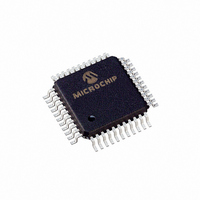
TC7116CKW713 Microchip Technology, TC7116CKW713 Datasheet - Page 6

TC7116CKW713
Manufacturer Part Number
TC7116CKW713
Description
IC ADC 3 1/2DGT LCD DVR 44-MQFP
Manufacturer
Microchip Technology
Datasheet
1.TC7116CPL.pdf
(24 pages)
Specifications of TC7116CKW713
Display Type
LCD
Configuration
7 Segment
Digits Or Characters
A/D 3.5 Digits
Current - Supply
800µA
Voltage - Supply
9V
Operating Temperature
0°C ~ 70°C
Mounting Type
Surface Mount
Package / Case
44-MQFP, 44-PQFP
Lead Free Status / RoHS Status
Lead free / RoHS Compliant
Interface
-
Available stocks
Company
Part Number
Manufacturer
Quantity
Price
Company:
Part Number:
TC7116CKW713
Manufacturer:
MICROCHIP
Quantity:
12 000
Company:
Part Number:
TC7116CKW713
Manufacturer:
Microchip Technology
Quantity:
10 000
TC7116/A/TC7117/A
2.0
The descriptions of the pins are listed in Table 2-1.
TABLE 2-1:
DS21457C-page 6
(40-Pin CERDIP)
(40-Pin PDIP)
Pin Number
10
11
12
13
14
15
16
17
18
19
20
21
22
23
24
25
26
27
28
29
30
31
32
33
1
2
3
4
5
6
7
8
9
PIN DESCRIPTIONS
PIN FUNCTION TABLE
(44-Pin PQFP)
Pin Number
10
12
13
14
15
16
17
18
19
20
21
22
23
24
25
26
27
28
29
30
31
32
34
35
36
37
38
39
40
41
11
8
9
COMMON This pin is primarily used to set the Analog Common mode voltage for battery
Symbol
HLDR
V
C
GND
POL
V
V
AB
C
V
BP/
BUFF
G
G
G
REF
D
C
B
A
F
E
D
C
B
A
F
E
D
B
F
E
A
C
V-
INT
IN
IN
AZ
1
1
1
1
1
1
2
2
2
2
2
2
3
3
3
3
3
3
1
3
2
4
+
-
-
Hold pin, Logic 1 holds present display reading.
Activates the D section of the units display.
Activates the C section of the units display.
Activates the B section of the units display.
Activates the A section of the units display.
Activates the F section of the units display.
Activates the G section of the units display.
Activates the E section of the units display.
Activates the D section of the tens display.
Activates the C section of the tens display.
Activates the B section of the tens display.
Activates the A section of the tens display.
Activates the F section of the tens display.
Activates the E section of the tens display.
Activates the D section of the hundreds display.
Activates the B section of the hundreds display.
Activates the F section of the hundreds display.
Activates the E section of the hundreds display.
Activates both halves of the 1 in the thousands display.
Activates the negative polarity display.
LCD backplane drive output (TC7116/TC7116A). Digital ground
(TC7117/TC7117A).
Activates the G section of the hundreds display.
Activates the A section of the hundreds display.
Activates the C section of the hundreds display.
Activates the G section of the tens display.
Negative power supply voltage.
Integrator output. Connection point for integration capacitor.
See Section 4.3 “Integrating Capacitor”, Integrating Capacitor for more
details.
Integration resistor connection. Use a 47kΩ resistor for a 200mV full scale range
and a 470kΩ resistor for 2V full scale range.
The size of the auto-zero capacitor influences system noise. Use a 0.47μF
capacitor for 200mV full scale, and a 0.047μF capacitor for 2V full scale.
See Section 4.1 “Auto-Zero Capacitor”, Auto-Zero Capacitor for more details.
The analog LOW input is connected to this pin.
The analog HIGH input signal is connected to this pin.
operation, or in systems where the input signal is referenced to the power sup-
ply. It also acts as a reference voltage source. See Section 3.1.6 “Analog Com-
mon”, Analog Common for more details.
See Pin 34.
Description
© 2006 Microchip Technology Inc.


