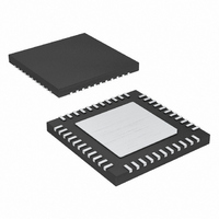
MAX6960ATH+T Maxim Integrated Products, MAX6960ATH+T Datasheet - Page 24

MAX6960ATH+T
Manufacturer Part Number
MAX6960ATH+T
Description
IC DRVR LED 8X8 44-TQFN
Manufacturer
Maxim Integrated Products
Datasheet
1.MAX6963ATH.pdf
(35 pages)
Specifications of MAX6960ATH+T
Display Type
LED
Configuration
8 x 8 (Matrix)
Interface
4-Wire Serial
Digits Or Characters
Any Digit Type
Current - Supply
7.5mA
Voltage - Supply
2.7 V ~ 3.6 V
Operating Temperature
-40°C ~ 125°C
Mounting Type
Surface Mount
Package / Case
44-TQFN Exposed Pad
Number Of Segments
64
Low Level Output Current
750 mA
High Level Output Current
48 mA
Operating Supply Voltage
2.7 V to 3.6 V
Maximum Supply Current
9 mA
Maximum Power Dissipation
2162 mW
Maximum Operating Temperature
+ 125 C
Mounting Style
SMD/SMT
Minimum Operating Temperature
- 40 C
Lead Free Status / RoHS Status
Lead free / RoHS Compliant
The planes/intensity (PI) control bit in the global panel
configuration register selects whether the display mem-
ory is configured as four planes with 1-bit-per pixel per
color-intensity control, or two planes with 2-bits-per
pixel per color-intensity control. This bit is fixed at zero
for the MAX6961 and MAX6963, and a write to this bit is
ignored for these parts.
The pixel intensity scale register (Table 24) sets the
graduation type used when 2-bits-per-pixel intensity
control is selected by setting the PI bit (Table 22). The
pixel level-intensity control can be set to be either
arithmetic (off, 1/3, 2/3, full) or geometric (off, 1/4, 1/2,
full). The setting is made on a digit-by-digit basis, so
each color on an RGY or RGB panel can use the most
appropriate graduation type.
The digit 0 and digit 1 intensity registers (Tables 25 and
26) set the fractions of the panel intensity PWM value
that are applied to the two display digits. The PWM for
each digit is calculated as n/256th of the panel intensity
value, where n is the value in the digit’s digit 0/1 intensi-
ty register. The digit 0/1 intensity registers enable con-
figuring relative adjustments in digit intensity, while the
4-Wire Serially Interfaced
8 x 8 Matrix Graphic LED Drivers
Table 27. Panel Intensity Register Format
Table 28. Global Driver Indirect Address Format
24
______________________________________________________________________________________
Global driver indirect address
255/256 (max on)
2/256 (min on)
REGISTER
REGISTER
251/256
252/256
253/256
254/256
3/256
4/256
5/256
—
Planes/Intensity Control (Bit D7)
Pixel Intensity Scale Register
Digit Intensity Control
ADDRESS CODE
ADDRESS CODE
(HEX)
0x02
0x02
0x02
0x02
0x02
0x02
0x02
0x02
0x02
0x02
0x02
0x02
(HEX)
0x08
MSB
D7
—
D7
0
0
0
0
0
0
1
1
1
1
1
display panel is still controlled as a whole by the panel
intensity. These adjustments are typically used to cali-
brate out luminosity differences between LEDs from dif-
ferent batches. They can also be used to color balance
RGY displays so that, for example, full panel intensity of
a red-green panel is a consistent orange hue.
Digital control of panel display brightness is provided
by an internal pulse-width modulator, which is con-
trolled by the panel intensity register (Table 27). The
modulator scales the average segment current in 253
steps from a maximum of 255/256 down to 2/256 of the
peak current. The maximum effective PWM duty cycle
for a digit is therefore 254/256, given by the maximum
255/256 digit intensity multiplied by the maximum
255/256 panel intensity. The minimum interdigit blank-
ing time is therefore 4/256 of a cycle, or 4/256 x 122µs
digit period = 1.91µs.
The LED drive current can be selected between either
a 40mA peak per segment and a lower 20mA peak cur-
rent on a digit-by-digit basis using the R
R
20mA, or connected to GND to select 40mA segment
current for digit 0. R
ISET1
D6
—
D6
0
0
0
0
0
0
1
1
1
1
1
8-bit driver indirect address 0x00 to 0xFF
pins. R
D5
—
D5
0
0
0
0
0
0
1
1
1
1
1
Peak-Segment Current Selection
ISET0
REGISTER DATA
REGISTER DATA
D4
—
D4
0
0
0
0
0
0
1
1
1
1
1
ISET1
should be open circuit to select
Panel Intensity Control
D3
selects segment current for
—
D3
0
0
0
0
0
0
1
1
1
1
1
D2
—
D2
0
0
0
0
1
1
0
1
1
1
1
D1
—
D1
0
0
1
1
0
0
1
0
0
1
1
ISET0
LSB
D0
—
D0
0
1
0
1
0
1
1
0
1
0
1
and


