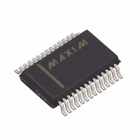
MAX6957AAI+ Maxim Integrated Products, MAX6957AAI+ Datasheet - Page 9

MAX6957AAI+
Manufacturer Part Number
MAX6957AAI+
Description
IC DRIVER LED PORT 20/28 28-SSOP
Manufacturer
Maxim Integrated Products
Datasheet
1.MAX6957ANI.pdf
(25 pages)
Specifications of MAX6957AAI+
Display Type
LED
Configuration
7, 16, 20 Segment
Interface
4-Wire Serial
Current - Supply
180µA
Voltage - Supply
2.5 V ~ 5.5 V
Operating Temperature
-40°C ~ 125°C
Mounting Type
Surface Mount
Package / Case
28-SSOP
Number Of Digits
7
Number Of Segments
7, 14, 16
Low Level Output Current
18000 uA
Operating Supply Voltage
2.5 V to 5.5 V
Maximum Supply Current
270 uA
Maximum Power Dissipation
727 mW
Maximum Operating Temperature
+ 125 C
Mounting Style
SMD/SMT
Minimum Operating Temperature
- 40 C
Lead Free Status / RoHS Status
Lead free / RoHS Compliant
Digits Or Characters
-
Lead Free Status / Rohs Status
Lead free / RoHS Compliant
Controlling the MAX6957 requires sending a 16-bit
word. The first byte, D15 through D8, is the command
address
D0, is the data byte (Table 4).
Multiple MAX6957s may be daisy-chained by connect-
ing the DOUT of one device to the DIN of the next, and
driving SCLK and CS lines in parallel (Figure 4). Data at
DIN propagates through the internal shift registers and
appears at DOUT 15.5 clock cycles later, clocked out
on the falling edge of SCLK. When sending commands
to multiple MAX6957s, all devices are accessed at the
same time. An access requires (16
where n is the number of MAX6957s connected togeth-
er. To update just one device in a daisy-chain, the user
can send the No-Op command (0x00) to the others.
Figure 4. Daisy-Chain Arrangement for Controlling Multiple MAX6957s
Figure 5. 16-Bit Write Transmission to the MAX6957
DOUT
SCLK
Connecting Multiple MAX6957s to the 4-Wire Bus
DIN
Control and Operation Using the
CS
28-Port LED Display Driver and I/O Expander
(Table 3), and the second byte, D7 through
MICROCONTROLLER
4-Wire-Interfaced, 2.5V to 5.5V, 20-Port and
SERIAL CLOCK OUTPUT
SERIAL DATA OUTPUT
SERIAL DATA INPUT
SERIAL CS OUTPUT
D15
= 0
_______________________________________________________________________________________
D14
D13
4-Wire Interface
D12
CS
SCLK
DIN
✕
D11
n) clock cycles,
MAX6957
D10
DOUT
D9
D8
The MAX6957 contains a 16-bit shift register into which
DIN data are clocked on the rising edge of SCLK, when
CS is low. When CS is high, transitions on SCLK have
no effect. When CS goes high, the 16 bits in the Shift
register are parallel loaded into a 16-bit latch. The 16
bits in the latch are then decoded and executed.
The MAX6957 is written to using the following
sequence:
1) Take SCLK low.
2) Take CS low. This enables the internal 16-bit shift
3) Clock 16 bits of data into DIN—D15 first, D0 last—
4) Take CS high (either while SCLK is still high after
5) Take SCLK low (if not already low).
Figure 5 shows a write operation when 16 bits are
transmitted.
D7
CS
SCLK
DIN
register.
observing the setup and hold times (bit D15 is low,
indicating a write command).
clocking in the last data bit, or after taking SCLK
low).
.
D6
MAX6957
D5
DOUT
D4
Writing Device Registers
D3
CS
SCLK
DIN
D2
MAX6957
D1
DOUT
D0
D15 = 0
9


