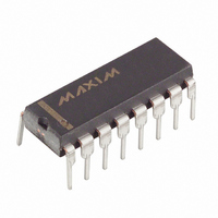
MAX6959AAPE+ Maxim Integrated Products, MAX6959AAPE+ Datasheet - Page 12

MAX6959AAPE+
Manufacturer Part Number
MAX6959AAPE+
Description
IC DRVR DSPL LED 16-DIP
Manufacturer
Maxim Integrated Products
Datasheet
1.MAX6958AAEE.pdf
(19 pages)
Specifications of MAX6959AAPE+
Display Type
LED
Configuration
7 Segment + 2 Annunciators
Interface
SMBus (2-Wire/I²C)
Digits Or Characters
4 Digits
Current - Supply
5.9mA
Voltage - Supply
3 V ~ 5.5 V
Operating Temperature
-40°C ~ 125°C
Mounting Type
Through Hole
Package / Case
16-DIP (0.300", 7.62mm)
Number Of Digits
4
Number Of Segments
36
Low Level Output Current
275 mA
High Level Output Current
30 mA
Operating Supply Voltage
3 V to 5.5 V
Maximum Supply Current
6.7 mA
Maximum Power Dissipation
842 mW
Maximum Operating Temperature
+ 125 C
Mounting Style
Through Hole
Minimum Operating Temperature
- 40 C
Lead Free Status / RoHS Status
Lead free / RoHS Compliant
Use the configuration register to enter and exit shut-
down, check device type, and globally clear the digit
data (Tables 10–13). The S bit selects shutdown or nor-
mal operation (read/write). The D bit reports whether
the device is a MAX6958 or a MAX6959 (read only).
The R bit clears all the digit and segment data (data is
not stored-transient bit)
The scan-limit register sets the number of digits dis-
played, from one to four (Table 14). A bicolor digit is
connected as two monocolor digits. The scan-limit reg-
ister also limits the number of keys that can be
2-Wire Interfaced, 3V to 5.5V, 4-Digit,
9-Segment LED Display Drivers with Keyscan
Table 10. Configuration Register Format
Table 11. Shutdown Control (S Data Bit D0) Format
Table 12. Device Readback (D Data Bit D1) Format
Table 13. Global Clear Digit Data (R Data Bit D5) Format
Table 14. Scan-Limit Register Format
12
Display digit 0 and segments 0, 4
Display digits 0, 1 and segments 0, 1, 4, 5
Display digits 0, 1, 2 and segments 0, 1, 2, 4, 5, 6
Display digits 0, 1, 2, 3 and segments 0, 1, 2, 3, 4,
5, 6, 7
______________________________________________________________________________________
Digit and segment data are unaffected
Digit and segment data are cleared
Configuration register
Normal operation
Shutdown mode
SCAN LIMIT
MAX6958
MAX6959
MODE
MODE
MODE
MODE
Configuration Register
Scan-Limit Register
CODE (HEX)
CODE (HEX)
CODE (HEX)
CODE (HEX)
CODE (HEX)
ADDRESS
ADDRESS
ADDRESS
ADDRESS
ADDRESS
0x04
0x04
0x04
0x04
0x04
0x04
0x04
0x03
0x03
0x03
0x03
scanned. Since the number of scanned digits affects
the display brightness, the scan-limit register should
not be used to blank portions of the display (such as
leading zero suppression).
An internal pulse-width modulator controlled by the
intensity register provides digital control of display
brightness. The modulator scales the average segment
current in 63 steps from a maximum of 63/64 down to
1/64 of the 23mA peak current. The minimum interdigit
blanking time is set to 1/64 of a cycle (Figure 11 and
Table 15).
D7
D7
D7
D7
D7
X
X
X
X
X
X
X
X
X
X
X
D6
X
X
X
X
D6
D6
D6
D6
X
X
X
X
X
X
X
D5
X
X
X
X
REGISTER DATA
D5
D5
D5
D5
R
R
R
R
R
0
1
D4
X
X
X
X
REGISTER DATA
REGISTER DATA
REGISTER DATA
REGISTER DATA
D4
D4
D4
D4
X
X
X
X
X
X
X
D3
X
X
X
X
D3
D3
D3
D3
X
X
X
X
X
D2
X
X
X
X
X
X
Intensity Register
D1
D2
D2
D2
D2
0
0
1
1
X
X
X
X
X
X
X
D0
0
1
0
1
D1
D1
D1
D1
D
D
D
0
1
D
D
CODE
HEX
0xX0
0xX1
0xX2
0xX3
D0
D0
D0
D0
S
S
S
0
1
S
S


