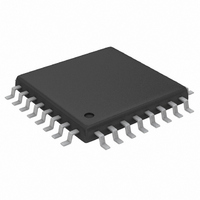
MAX3668EHJ Maxim Integrated Products, MAX3668EHJ Datasheet - Page 3

MAX3668EHJ
Manufacturer Part Number
MAX3668EHJ
Description
IC LSR DRVR 622MBPS 3.63V 32TQFP
Manufacturer
Maxim Integrated Products
Type
Laser Diode Driver (Fiber Optic)r
Datasheet
1.MAX3668EHJ.pdf
(12 pages)
Specifications of MAX3668EHJ
Data Rate
622Mbps
Number Of Channels
1
Voltage - Supply
3.14 V ~ 5.5 V
Current - Supply
38mA
Current - Modulation
75mA
Current - Bias
80mA
Operating Temperature
-40°C ~ 85°C
Package / Case
32-TQFP, 32-VQFP
Mounting Type
Surface Mount
Operating Supply Voltage
3.3 V
Supply Current
38 mA
Maximum Power Dissipation
929 mW
Mounting Style
SMD/SMT
Lead Free Status / RoHS Status
Contains lead / RoHS non-compliant
Available stocks
Company
Part Number
Manufacturer
Quantity
Price
Part Number:
MAX3668EHJ
Manufacturer:
MAXIM/美信
Quantity:
20 000
Company:
Part Number:
MAX3668EHJ+
Manufacturer:
Maxim Integrated
Quantity:
10 000
Company:
Part Number:
MAX3668EHJ+T
Manufacturer:
Maxim Integrated
Quantity:
10 000
Company:
Part Number:
MAX3668EHJ-T
Manufacturer:
Maxim Integrated
Quantity:
10 000
AC ELECTRICAL CHARACTERISTICS
(V
T
Figure 1. Required Input Signal and Output Polarity
Note 1: Characteristics at -40°C are guaranteed by design and characterization. Dice are tested at T
Note 2: Tested with R
Note 3: Both the bias and modulation currents will be disabled if any of the current set pins are shorted to ground.
Note 4: This assumes that the laser to monitor diode transfer function does not change with temperature.
Note 5: See Typical Operating Characteristics for worst-case distributions.
Note 6: AC characteristics are guaranteed by design and characterization.
Note 7: Total I
Note 8: Input signal is a 622Mbps, 2
Note 9: Input signal is a 622Mbps, 11110000 pattern.
Note 10:PWD = (wider pulse – narrower pulse) / 2.
A
Modulation Current Range
Modulation Off Current
Modulation Current Stability
Modulation Current Absolute
Accuracy
Output Rise/Fall Time
Jitter Generation (peak-to-peak)
Pulse-Width Distortion
(peak-to-peak)
Enable/Start-Up Delay
Maximum Consecutive Identical
Digits at 622Mbps
(DATA+) -
CC
= +25°C.) (Note 6)
(DATA-)
DATA+
DATA-
I
= +3.14V to +5.5V, load as shown in Figure 2, T
OUT
+
PARAMETER
Laser Driver with Automatic Power Control
MOD
out of OUT+. Refer to the Design Procedure for information regarding current delivered to the laser.
_______________________________________________________________________________________
MODSET
= 5.11kΩ (I
SYMBOL
I
13
t
MOD
CID
R/
- 1 PRBS with 80 inserted zeros.
t
F
MOD
(Note 7)
ENABLE = low (Note 3)
I
I
20% to 80%,
R
(Note 8)
(Notes 9, 10)
Open loop
≈ 38mA), R
MOD
MOD
L
200mVp-p MIN
1600mVp-p MAX
I
100mV MIN
800mV MAX
MOD
= 10Ω
= 75mA
= 5mA (Note 5)
A
+3.3V, 622Mbps SDH/SONET
= -40°C to +85°C, unless otherwise noted. Typical values are at V
| |
BIASMAX
20Ω load
CONDITIONS
= 4.56kΩ (I
Figure 2. Output Termination for Characterization
MAX3668
I
I
I
I
MOD
MOD
MOD
MOD
BIAS
= 5mA
= 75mA
= 5mA
= 75mA
OUT+
OUT-
BIAS
≈ 52mA), excluding I
20Ω
V
V
CC
20Ω
CC
15Ω
-620
MIN
-15
80
5
1.0µF
1.0µF
A
= +25°C only.
12.4Ω
BIAS
TYP
175
300
100
230
250
70
10
and I
10Ω
MOD
MAX
200
620
200
375
100
155
135
OSCILLOSCOPE
75
15
.
CC
= +3.3V,
ppm/°C
UNITS
50Ω
Bits
mA
µA
ps
ps
ps
ns
%
3


