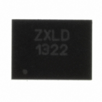
ZXLD1322DCCTC Diodes Zetex, ZXLD1322DCCTC Datasheet

ZXLD1322DCCTC
Specifications of ZXLD1322DCCTC
Related parts for ZXLD1322DCCTC
ZXLD1322DCCTC Summary of contents
Page 1
BUCK/BOOST MODE DC-DC CONVERTER FOR LED DRIVING WITH 700mA OUTPUT AND CURRENT Description The ZXLD1322 is an inductive DC-DC converter, with an internal switch, designed for driving single or multiple LEDs in series total of 700mA output ...
Page 2
Block Diagram ZXLD1322 Document number: DS32166 Rev Product Line of Diodes Incorporated www.diodes.com ZXLD1322 April 2010 © Diodes Incorporated ...
Page 3
Pin Description Name Pin # Adjust input • Leave floating, or connect to V • Drive with dc voltage. (50mV<V ADJ 1 of set value. (DC brightness control mode) • Drive with low frequency (200Hz) PWM control signal to gate ...
Page 4
Absolute Maximum Ratings Symbol Parameter Operating Temperature T OP Storage Temperature T ST Junction Temperature T J Package Power Dissipation P TOT DFN14 with Exposed Pad: 4mm x 3mm, 0.5mm Pitch DC-DC Converter Supply Voltage (VIN) -0.3V to +15V ADJ ...
Page 5
Electrical Characteristics (Test conditions: V DC-DC Converter Supply Parameters Symbol Parameter Supply Voltage V IN Supply voltage for start-up(b) V IN(Start) Under-voltage detection threshold normal operation to start-up mode Under-voltage detection threshold start-up mode ...
Page 6
Switching NPN Transistor Symbol Parameter Average continuous switch current I SW Maximum base current into switch I BON(max) transistor from internal drive circuit Base current into switch transistor I using external resistor (R BON BIAS pin to ground Collector-Emitter breakdown ...
Page 7
LED Thermal Control Circuit (T ADJ Symbol Parameter Upper threshold voltage VT ADJH Lower threshold voltage VT ADJL Trans conductance Gm (TADJ) ΔI /ΔV OUT TADJ Output Current Regulation Parameters Symbol Parameter Minimum output/ LED current I OUT ΔI Output ...
Page 8
Device Description The ZXLD1322 is a buck/boost mode inductive DC-DC converter, with an internal switch, designed for driving single or multiple LEDs in series total of 700mA output current. Depending upon supply voltage (V drop (V ) ...
Page 9
ADJ pin The ADJ pin is connected to the internal 500mV reference (V reference voltage and defines nominal 100% LED current. The ADJ pin can be overdriven with an external dc voltage between 50mV and 500mV to reduce the LED ...
Page 10
Application Notes Setting Peak Coil Current The peak current in the coil is set by the resistor (RSENSE) between the switch emitter and ground according to: 50mV I SWPEAK = R SENSE The minimum peak current will depend on operating ...
Page 11
PWM Control A wider dimming range can be achieved by applying a PWM control signal to the ADJ pin to turn the device on and off, giving an average output current proportional to the duty cycle of the control signal. ...
Page 12
The TADJ pin of the device has a voltage threshold of 75mV nominal, which is derived from the reference voltage V the voltage ( the TADJ pin is held above the threshold, the thermal compensation current will be ...
Page 13
Typical Operating Conditions Inductive converters can operate in either CONTINUOUS mode, where current always flows ithe inductor, but rises during the ON period and falls during the OFF period, or DISCONTINUOUS mode, where the current falls to zero during the ...
Page 14
ON phase, the current can still be established when the supply is less than the LED forward drop. Hence this circuit will work at supply voltages above and below the forward LED drop. This mode is useful for example ...
Page 15
... The bottom of the thermistor must be coupled very closely to ground, as the TADJ pin varies the LED current from 100 for a voltage change of only 25mV, so any noise on the bottom of the thermistor will seriously affect the accuracy of the Thermal Protection circuit. Ordering Information Reel Size Device (mm) ZXLD1322DCCTC 33.02 ZXLD1322 Document number: DS32166 Rev Product Line of Diodes Incorporated Reel Width ...
Page 16
Package Outline – DFN4030-14 E PIN 1 DOT BY MARKING DIM Inches Min Max Min A 0.0315 0.0354 0.80 A1 0.00 0.002 0.00 A3 0.008 REF. b 0.0079 0.0118 0.20 D 0.1555 0.1594 3.95 Note: Controlling dimensions are in millimeters. ...
Page 17
DIODES INCORPORATED MAKES NO WARRANTY OF ANY KIND, EXPRESS OR IMPLIED, WITH REGARDS TO THIS DOCUMENT, INCLUDING, BUT NOT LIMITED TO, THE IMPLIED WARRANTIES OF MERCHANTABILITY AND FITNESS FOR A PARTICULAR PURPOSE (AND THEIR EQUIVALENTS UNDER THE LAWS OF ANY ...


