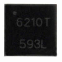
A6210GEUTR-T Allegro Microsystems Inc, A6210GEUTR-T Datasheet - Page 5

A6210GEUTR-T
Manufacturer Part Number
A6210GEUTR-T
Description
IC LED DRIVER HIGH BRIGHT 16-QFN
Manufacturer
Allegro Microsystems Inc
Type
HBLED Driverr
Datasheet
1.A6210GEUTR-T.pdf
(11 pages)
Specifications of A6210GEUTR-T
Topology
PWM, Step-Down (Buck), Switched Capacitor (Charge Pump)
Number Of Outputs
1
Internal Driver
Yes
Type - Secondary
High Brightness LED (HBLED)
Frequency
100kHz ~ 2 MHz
Voltage - Supply
9 V ~ 46 V
Voltage - Output
46V
Mounting Type
Surface Mount
Package / Case
16-WSQFN Exposed Pad
Operating Temperature
-40°C ~ 105°C
Current - Output / Channel
3A
Internal Switch(s)
Yes
Efficiency
90%
Led Driver Application
Power Supplies And Lamps
No. Of Outputs
1
Output Current
3A
Output Voltage
46V
Input Voltage
9V To 46V
Dimming Control Type
PWM
Lead Free Status / RoHS Status
Lead free / RoHS Compliant
Other names
620-1281-2
Available stocks
Company
Part Number
Manufacturer
Quantity
Price
Company:
Part Number:
A6210GEUTR-T
Manufacturer:
ROHM
Quantity:
5 160
Part Number:
A6210GEUTR-T
Manufacturer:
ALLEGRO/雅丽高
Quantity:
20 000
A6210
Basic Operation
The A6210 is a buck regulator that utilizes valley current mode
control. The on-time is set by the amount of current that flows
into the TON pin. This is determined by the value of the TON
resistor chosen (R1 in the Functional Block diagram) and the
magnitude of the input voltage, V
conditions, an on-time can be set that then dictates the switching
frequency. This switching frequency remains reasonably con-
stant throughout load and line conditions as the on-time varies
inversely with the input voltage.
At the beginning of the switching cycle, the buck switch is turned
on for a fixed period that is determined by the current flowing
into TON. Once the current comparator trips, a one-shot mono-
stable, the On Timer, is reset, turning off the switch. The current
through the inductor then decays. This current is sensed through
the external sense resistor (R2), and then compared against the
current-demand signal. After the current through the sense resis-
tor decreases to the valley of the current-demand signal, the On
Timer is set to turn the buck switch back on again and the cycle is
repeated.
Disable/Enable The regulator is enabled by pulling the DIS pin
low. To disable the regulator, the DIS pin can simply be discon-
nected (open circuit).
Shutdown The regulator is disabled in the event of either an
overtemperature event, or an undervoltage on VIN (V
an internal housekeeping supply.
As soon as any of the above faults have been removed and
assuming DIS = 0, the output is restored.
Switch On Time and Switching Frequency The switch
on-time effectively determines the operating frequency of the
converter. To minimize the size of the power inductor and input
filtering it is recommended to run with as high a frequency
as possible. The MOSFET drivers are optimized to minimize
switching losses.
An important consideration in selecting the switching frequency
is to ensure that the on time (60 ns) and off time (350 ns) limita-
tions are not reached under extreme conditions:
• the minimum on time occurs at maximum input voltage
• the maximum off time occurs at minimum input voltage
The following table takes into account the above maximum off
time figure and outlines the typical switching frequencies that can
IN
. Under a specific set of
Functional Description
3 A, 2 MHz Buck-Regulating LED Driver
INUV
) or on
be achieved for a given number of LEDs and input voltage. Note
that it is highly recommended that worst case values are used
when considering any design.
The switch on time is programmed by the current flowing into
the TON pin. The current is determined by the input voltage, V
and the resistor, R1. The on time, T
To calculate the actual switching frequency, f
above calculation can be used in conjunction with the transfer
function of the converter, as follows:
A simplified approach to selecting the T
accomplish an approximate switching frequency, can be found
from the following formula:
Figure 1 illustrates a range of switching frequencies that can be
achieved with a given resistor and LED voltage. Each LED is
assumed to have a voltage drop of 3.5 V.
High Brightness LED Driving
The A6210 can be configured as a very simple, low cost, high
brightness LED driver. The solution can drive high brightness
LEDs up to more than 3 A, while achieving very high efficien-
cies, in excess of 90%.
The solution uses valley current mode control. This architecture
is optimized for high switching frequencies, allowing the use
Frequency
Switching
(MHz)
2.0
1.7
1.0
0.300
T
f
R
SW
on
1
=
=
Quantity
of LEDs
=
V
1
1
2
3
V
V
IN
V
IN
OUT
12 V
IN
× 2.05 × 10
× 2.05 × 10
+ V
Voltage
f
+ V
SW
Span
LED
10.5
R
(V)
3.5
3.5
7.0
f
1
f
115 Northeast Cutoff
1.508.853.5000; www.allegromicro.com
Allegro MicroSystems, Inc.
Worcester, Massachusetts 01615-0036 U.S.A.
×
Quantity
of LEDs
10
T
10
1
Input Voltage
on
2
3
4
6
on
24 V
+
, can be found:
.
10 × 10
.
on
Voltage
Span
LED
10.5
14.0
21.0
(V)
resistor (R1), to
7.0
sw
–9
, the T
Quantity
of LEDs
.
3
4
6
9
on
36 V
from the
Voltage
Span
LED
10.5
14.0
21.0
31.5
(V)
(1)
(2)
(3)
IN
5
,


