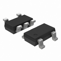
CAT4240TD-GT3 ON Semiconductor, CAT4240TD-GT3 Datasheet - Page 10

CAT4240TD-GT3
Manufacturer Part Number
CAT4240TD-GT3
Description
IC LED DRVR WHITE BCKLGHT TSOT-5
Manufacturer
ON Semiconductor
Type
Backlight, White LEDr
Datasheet
1.CAT4240TD-GT3.pdf
(12 pages)
Specifications of CAT4240TD-GT3
Constant Current
Yes
Topology
PWM, Step-Up (Boost)
Number Of Outputs
1
Internal Driver
Yes
Type - Primary
Backlight
Type - Secondary
White LED
Frequency
800kHz ~ 1.3MHz
Voltage - Supply
2.8 V ~ 5.5 V
Voltage - Output
38V
Mounting Type
Surface Mount
Package / Case
TSOT-23-5, TSOT-5, TSOP-5
Operating Temperature
-40°C ~ 85°C
Current - Output / Channel
60mA
Internal Switch(s)
Yes
Efficiency
94%
Number Of Segments
10
High Level Output Current
750 mA
Operating Supply Voltage
2 V to 5.5 V
Maximum Supply Current
1.5 mA
Maximum Operating Temperature
+ 85 C
Mounting Style
SMD/SMT
Minimum Operating Temperature
- 40 C
Lead Free Status / RoHS Status
Lead free / RoHS Compliant
Other names
4240TD-GT3
CAT4240TD-GT3TR
CAT4240TD-GT3TR
Available stocks
Company
Part Number
Manufacturer
Quantity
Price
Company:
Part Number:
CAT4240TD-GT3
Manufacturer:
AD
Quantity:
569
Board Layout
The traces that carry the high−frequency switching current
have to be carefully laid out on the board in order to
minimize EMI, ripple and noise in general. The thicker lines
on Figure 26 show the switching current path. All these
traces have to be short and wide enough to minimize the
parasitic inductance and resistance. The loop shown on
Figure 26 corresponds to the current path when the
CAT4240 internal switch is closed. On Figure 27 is shown
V
The CAT4240 is a high−frequency switching regulator.
C
IN
1
Figure 26. Closed−switch Current Loop
SHDN
VIN
L
CAT4240
GND
SW
Switch
Closed
FB
Figure 28. Recommended PCB Layout
D
C
2
V
OUT
http://onsemi.com
R1
10
V
the current loop, when the CAT4240 switch is open. Both
loop areas should be as small as possible.
V
separately to the top LED anode. A ground plane under the
CAT4240 allows for direct connection of the capacitors to
ground. The resistor R
GND pin of the CAT4240 and not shared with the switching
current loops and any other components.
C
IN
IN
1
Capacitor C
pin and GND. The capacitor C
SHDN
Figure 27. Open−switch Current Loop
VIN
L
1
has to be placed as close as possible to the
CAT4240
GND
1
must be connected directly to the
SW
Switch
Open
2
FB
has to be connected
D
C
2
V
OUT
R1


