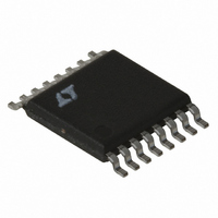
LT3518EFE#PBF Linear Technology, LT3518EFE#PBF Datasheet

LT3518EFE#PBF
Specifications of LT3518EFE#PBF
Available stocks
Related parts for LT3518EFE#PBF
LT3518EFE#PBF Summary of contents
Page 1
... L, LT, LTC and LTM are registered trademarks of Linear Technology Corporation. True Color PWM is a trademark of Linear Technology Corporation. Patent Pending. All other trademarks are the property of their respective owners. Protected by U.S. Patents, including 7199560, 7321203, 7746300 ...
Page 2
... ORDER INFORMATION LEAD FREE FINISH TAPE AND REEL LT3518EUF#PBF LT3518EUF#TRPBF LT3518IUF#PBF LT3518IUF#TRPBF LT3518EFE#PBF LT3518EFE#TRPBF LT3518IFE#PBF LT3518IFE#TRPBF LT3518HFE#PBF LT3518HFE#TRPBF Consult LTC Marketing for parts specified with wider operating temperature ranges. *The temperature grade is identified by a label on the shipping container. Consult LTC Marketing for information on non-standard lead based finish parts. ...
Page 3
ELECTRICAL CHARACTERISTICS temperature range, otherwise specifications are at T PARAMETER Minimum V Operating Voltage IN Maximum V Operating Voltage IN Current Sense Voltage (V – ISP ISN 10% Scale Current Sense Voltage (V – V ISP ISN Current ...
Page 4
LT3518 ELECTRICAL CHARACTERISTICS temperature range, otherwise specifications are at T PARAMETER TGEN Input High Voltage TGEN Input Low Voltage TGEN Pin Bias Current V Pin Voltage REF V Pin Voltage Line Regulation REF Gate Turn-On Delay Gate Turn-Off Delay Top ...
Page 5
TYPICAL PERFORMANCE CHARACTERISTICS V – V Threshold vs V ISP ISN CTRL 120 24V ISP 100 25° 0.2 0.4 0.6 0.8 ...
Page 6
LT3518 TYPICAL PERFORMANCE CHARACTERISTICS FB Pin Threshold vs Temperature 1. 1.03 1.02 1.01 1.00 0.99 0.98 –40 – 100 120 140 160 TEMPERATURE (°C) 3518 G10 PIN FUNCTIONS SW: Switch Pin. ...
Page 7
BLOCK DIAGRAM R SENSE PV IN ISP ISN + – CURRENT X10 SENSE AMPLIFIER SHDN – CTRL + 1.01V A2 FB – SYNC + A5 – 10µ ...
Page 8
LT3518 OPERATION The LT3518 is a constant frequency, current mode regula- tor with an internal power switch. Operation can be best understood by referring to the Block Diagram in Figure 1. At the start of each oscillator cycle, the SR ...
Page 9
APPLICATIONS INFORMATION Dimming Control There are two methods to control the current source for dimming using the LT3518. The first method uses the PWM pin to modulate the current source between zero and full current to achieve a precisely programmed ...
Page 10
LT3518 APPLICATIONS INFORMATION For a buck or a buck-boost configuration, the output voltage is typically level-shifted to a signal with respect to GND as illustrated in the Figure 4. The output can be expressed as • 1.01V ...
Page 11
APPLICATIONS INFORMATION Use only ceramic capacitors with X7R, X5R or better dielec- tric as they are best for temperature and DC bias stability of the capacitor value. All ceramic capacitors exhibit loss of capacitance value with increasing DC voltage bias, ...
Page 12
LT3518 APPLICATIONS INFORMATION Switching Frequency There are two methods to set the switching frequency of LT3518. Both methods require a resistor connected at R pin. Do not leave the R pin open. Also, do not load this pin T with ...
Page 13
TYPICAL APPLICATIONS Buck Mode 1.5A LED Driver R SENSE M1 68m PV IN 24V C2 2.2µF ISP ISN 3.3V C1 SHDN 2.2µF LT3518 V CTRL FB REF PWM PWM SS SYNC R T TGEN ...
Page 14
LT3518 TYPICAL APPLICATIONS 16V C1 2.2µF C1: KEMET C0806C225K4RAC C2: KEMET C1206C475K3RAC C3, C4: MURATA GRM21BR71H104KA01B C5: MURATA GRM21BR71H224KA01B D1: ZETEX ZLLS2000TA L1: TOKO B992AS-4R3N LEDS: LUXEON I (WHITE) M1: ZETEX ZXMP6A13GTA 3000:1 PWM Dimming at ...
Page 15
TYPICAL APPLICATIONS Buck Mode 1A LED Driver with Open LED Protection and Sync Input PV IN 32V C2 2.2µ 3.3V C1 2.2µF V REF PWM SYNC 3.3V, 1.2MHz 1000:1 PWM Dimming at 120Hz PWM 5V/DIV I LED 1A/DIV ...
Page 16
LT3518 TYPICAL APPLICATIONS 16V PWM C1 2.2µF C4 0.1µF 3000:1 PWM Dimming at 100Hz PWM 5V/DIV I LED 200mA/DIV I L1 1A/DIV V = 12V 1µs/DIV 1MHz OSC I = 300mA LED 16 ...
Page 17
PACKAGE DESCRIPTION 4.35 ± 0.05 2.15 ± 0.05 (4 SIDES) 2.90 ± 0.05 RECOMMENDED SOLDER PAD PITCH AND DIMENSIONS 4.00 ± 0.10 (4 SIDES) PIN 1 TOP MARK (NOTE 6) NOTE: 1. DRAWING CONFORMS TO JEDEC PACKAGE OUTLINE MO-220 VARIATION ...
Page 18
LT3518 PACKAGE DESCRIPTION (.108) 6.60 ±0.10 4.50 ±0.10 SEE NOTE 4 RECOMMENDED SOLDER PAD LAYOUT 4.30 – 4.50* (.169 – .177) 0.09 – 0.20 0.50 – 0.75 (.0035 – .0079) (.020 – .030) NOTE: 1. CONTROLLING DIMENSION: MILLIMETERS MILLIMETERS 2. ...
Page 19
... Revised Electrical Characteristics Information furnished by Linear Technology Corporation is believed to be accurate and reliable. However, no responsibility is assumed for its use. Linear Technology Corporation makes no representa- tion that the interconnection of its circuits as described herein will not infringe on existing patent rights. LT3518 PAGE NUMBER ...
Page 20
... Dimming = 1000:1 True Color PWM, OUT(MAX) = 45V, Dimming = 3000:1 True Color PWM, OUT(MAX) = 45V, Dimming = 5000:1 True Color PWM, OUT(MAX) = Ext FET, Dimming = 3000:1 True Color PWM, OUT(MAX) LT 0111 REV D • PRINTED IN USA LINEAR TECHNOLOGY CORPORA TION 2007 < 1µA, 3518fd ...


