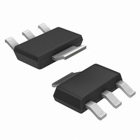
NSI45030ZT1G ON Semiconductor, NSI45030ZT1G Datasheet - Page 2

NSI45030ZT1G
Manufacturer Part Number
NSI45030ZT1G
Description
IC CCR/LED DVR 45V 30MA SOT223-4
Manufacturer
ON Semiconductor
Type
Linear (Non-Switching)r
Specifications of NSI45030ZT1G
Constant Current
Yes
Topology
High Side, Linear, Low Side
Number Of Outputs
1
Type - Primary
Automotive, Backlight
Voltage - Supply
45V
Mounting Type
Surface Mount
Package / Case
SOT-223 (3 leads + Tab), SC-73, TO-261
Operating Temperature
-55°C ~ 150°C
Current - Output / Channel
30mA
Internal Switch(s)
No
Lead Free Status / RoHS Status
Lead free / RoHS Compliant
Voltage - Output
-
Frequency
-
Efficiency
-
Lead Free Status / Rohs Status
Details
Available stocks
Company
Part Number
Manufacturer
Quantity
Price
Company:
Part Number:
NSI45030ZT1G
Manufacturer:
ON
Quantity:
10
Company:
Part Number:
NSI45030ZT1G
Manufacturer:
ON Semiconductor
Quantity:
350
1. I
2. V
3. I
4. f = 1 MHz, 0.02 V RMS.
5. FR−4 @ 100 mm
6. FR−4 @ 100 mm
7. FR−4 @ 300 mm
8. FR−4 @ 300 mm
9. FR−4 @ 500 mm
10. FR−4 @ 500 mm
NOTE: Lead measurements are made by non−contact methods such as IR with treated surface to increase emissivity to 0.9.
ELECTRICAL CHARACTERISTICS
THERMAL CHARACTERISTICS
Steady State Current @ Vak = 7.5 V (Note 1)
Voltage Overhead (Note 2)
Pulse Current @ Vak = 7.5 V (Note 3)
Capacitance @ Vak = 7.5 V (Note 4)
Capacitance @ Vak = 0 V (Note 4)
Total Device Dissipation (Note 5) T
Thermal Resistance, Junction−to−Ambient (Note 5)
Thermal Reference, Junction−to−Lead 4 (Note 5)
Total Device Dissipation (Note 6) T
Thermal Resistance, Junction−to−Ambient (Note 6)
Thermal Reference, Junction−to−Lead 4 (Note 6)
Total Device Dissipation (Note 7) T
Thermal Resistance, Junction−to−Ambient (Note 7)
Thermal Reference, Junction−to−Lead 4 (Note 7)
Total Device Dissipation (Note 8) T
Thermal Resistance, Junction−to−Ambient (Note 8)
Thermal Reference, Junction−to−Lead 4 (Note 8)
Total Device Dissipation (Note 9) T
Thermal Resistance, Junction−to−Ambient (Note 9)
Thermal Reference, Junction−to−Lead 4 (Note 9)
Total Device Dissipation (Note 10) T
Thermal Resistance, Junction−to−Ambient (Note 10)
Thermal Reference, Junction−to−Lead 4 (Note 10)
Junction and Storage Temperature Range
Derate above 25°C
Derate above 25°C
Derate above 25°C
Derate above 25°C
Derate above 25°C
Derate above 25°C
reg(SS)
reg(P)
overhead
Lead temperature measurement by attaching a T/C may yield values as high as 30% higher °C/W values based upon empirical
measurements and method of attachment.
non−repetitive pulse test. Pulse width t ≤ 300 msec.
steady state is the voltage (Vak) applied for a time duration ≥ 10 sec, using FR−4 @ 300 mm
= V
in
− V
2
2
2
2
2
2
, 1 oz. copper traces, still air.
, 2 oz. copper traces, still air.
, 1 oz. copper traces, still air.
, 2 oz. copper traces, still air.
, 1 oz. copper traces, still air.
, 2 oz. copper traces, still air.
LEDs
. V
overhead
Characteristic
A
A
A
A
A
Characteristic
is typical value for 70% I
A
= 25°C
= 25°C
= 25°C
= 25°C
= 25°C
= 25°C
(T
A
= 25°C unless otherwise noted)
http://onsemi.com
reg(SS)
.
2
V
Symbol
I
overhead
reg(SS)
I
reg(P)
C
C
Symbol
T
R ψ
R ψ
R ψ
R ψ
R ψ
R ψ
R
R
R
R
R
R
J
P
P
P
P
P
P
, T
θ
θ
θ
θ
θ
θ
D
D
D
D
D
D
25.5
26.7
JA
JL4
JA
JL4
JA
JL4
JA
JL4
JA
JL4
JA
JL4
Min
stg
2
2 oz. Copper traces, in still air.
−55 to +150
31.55
Typ
1.8
2.6
6.9
30
1074
1150
1300
1214
1389
Max
40.8
39.9
10.4
39.4
40.2
11.1
37.7
954
131
116
109
103
7.6
8.6
9.2
9.7
42
96
90
Max
34.5
36.4
mW/°C
mW/°C
mW/°C
mW/°C
mW/°C
mW/°C
°C/W
°C/W
°C/W
°C/W
°C/W
°C/W
°C/W
°C/W
°C/W
°C/W
°C/W
°C/W
Unit
mW
mW
mW
mW
mW
mW
°C
Unit
mA
mA
pF
pF
V


