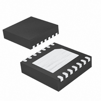
MAX8630WETD20+T Maxim Integrated Products, MAX8630WETD20+T Datasheet - Page 9

MAX8630WETD20+T
Manufacturer Part Number
MAX8630WETD20+T
Description
IC LED DRVR WHITE BCKLGT 14-TDFN
Manufacturer
Maxim Integrated Products
Type
Backlight, White LEDr
Datasheet
1.MAX8630XETD20T.pdf
(12 pages)
Specifications of MAX8630WETD20+T
Constant Current
Yes
Topology
PWM, Switched Capacitor (Charge Pump)
Number Of Outputs
5
Internal Driver
Yes
Type - Primary
Backlight
Type - Secondary
White LED
Frequency
1MHz
Voltage - Supply
2.7 V ~ 5.5 V
Voltage - Output
5V
Mounting Type
Surface Mount
Package / Case
14-TDFN Exposed Pad
Operating Temperature
-40°C ~ 85°C
Current - Output / Channel
25mA
Internal Switch(s)
Yes
Efficiency
93%
Lead Free Status / RoHS Status
Lead free / RoHS Compliant
When both ENM and ENS (or PWM) are held low for
4ms or longer, the MAX8630_ is shut down and put in a
low-current mode. OUT is internally pulled to GND with
5kΩ during shutdown.
If any LED fails as an open circuit, the corresponding
V
about 5V by gating on/off the charge pump. In case
any LED_ is floating or grounded, the MAX8630_ oper-
ates in the same overvoltage protection mode. To avoid
overvoltage protection mode when using fewer than
five LEDs, connect any unused LED_ to OUT. The
MAX8630_ contains special circuitry to detect this con-
dition and disables the corresponding current regulator
to avoid wasting battery current.
The MAX8630_ includes a thermal-protection circuit
that shuts down the IC when the die temperature reach-
es about +160°C. The part turns on after the IC cools
by approximately 20°C.
The MAX8630 contains a derating function that auto-
matically limits the LED current at high temperatures in
accordance with the recommended derating curve of
popular white LEDs. The derating function enables the
safe usage of higher LED currents at room tempera-
ture, thus reducing the number of LEDs required to
backlight the display. The derating circuit protects the
LEDs from overheating at high PCB temperatures. The
derating circuit limits the LED current by reducing the
internal 600mV reference voltage above +40°C at
approximately -1.67%/°C. The typical derating function
characteristic is shown in the Typical Operating
Characteristics.
Table 1. Recommended Components
LED_
125mA 1x/1.5x Charge Pumps for 5 White LEDs
C
DESIGNATION
IN
, C
goes to 0V, and the output voltage is limited to
D1–D5
OUT
, C1, C2
Temperature Derating Function
_______________________________________________________________________________________
VALUE
1µF
—
Overvoltage Protection
Thermal Shutdown
MANUFACTURER
Shutdown Mode
Taiyo Yuden
Nichia
TDK
C1005X5R0J105M
JMK105 BJ105MV
PART NUMBER
NSCW215T
To avoid overvoltage protection mode when using
fewer than five LEDs, connect any unused LED_ to
OUT. The MAX8630_ contains special circuitry to
detect this condition and disables the corresponding
current regulator to avoid wasting battery current.
For LED drivers, input ripple is more important than out-
put ripple. Input ripple depends on the source supply’s
output impedance. Adding a lowpass filter to the input
of the MAX8630_ further reduces input ripple.
Alternatively, increasing C
input ripple in half (or in fourth) with only a small
increase in footprint. The 1x mode always has very low
input ripple.
Ceramic capacitors are recommended due to their
small size, low cost, and low ESR. Select ceramic
capacitors that maintain their capacitance over temper-
ature and DC bias. Capacitors with X5R or X7R temper-
ature characteristics generally perform well. See Table
1 for a list of recommended components. Using a larg-
er value input capacitor helps to reduce input ripple
(see the Input Ripple section).
The MAX8630_ is a high-frequency, switched-capacitor
voltage regulator. For best circuit performance, use a
solid ground plane and place C
as close to the MAX8630_ as possible. See the
MAX8630_ evaluation kit for an example layout.
PROCESS: BiCMOS
in 3mm x 3mm TDFN
1µF ±20%, 6.3V X5R ceramic capacitors (0402)
1µF ±20%, 6.3V X5R ceramic capacitors (0402)
White LEDs
Applications Information
Driving Fewer than 5 LEDs
PCB Layout and Routing
DESCRIPTION
IN
Component Selection
Chip Information
to 2.2µF (or 4.7µF) cuts
IN
, C
OUT
Input Ripple
, C1, and C2
9


