VLA536-01R Powerex Inc, VLA536-01R Datasheet - Page 2
VLA536-01R
Manufacturer Part Number
VLA536-01R
Description
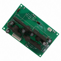
BOARD INTERFACE NX-SERIES
Manufacturer
Powerex Inc
Type
IGBTr
Datasheet
1.VLA536-01R.pdf
(4 pages)
Specifications of VLA536-01R
Current
5A
Voltage
18V
Voltage - Isolation
2500Vrms
Package / Case
Module
Mounting Type
Surface Mount
Voltage - Supply
12 V ~ 18 V
Operating Temperature
-20°C ~ 70°C
Number Of Outputs
2
Input Type
Non-Inverting
Delay Time
0.45µs
Current - Peak
5A
Number Of Configurations
1
Device Type
IGBT
Peak Output Current
-5A
Output Resistance
2ohm
Input Delay
6.5µs
Supply Voltage Range
12V To 18V
No. Of Pins
7
Operating Temperature Range
-20°C To +70°C
Rohs Compliant
Yes
Lead Free Status / RoHS Status
Lead free by exemption / RoHS compliant by exemption
Configuration
-
High Side Voltage - Max (bootstrap)
-
Lead Free Status / RoHS Status
Lead free by exemption / RoHS compliant by exemption
Other names
835-1067
Q4703491
VLA536-01R
Q4703491
VLA536-01R


2
Powerex, Inc., 173 Pavilion Lane, Youngwood, Pennsylvania 15697 (724) 925-7272
VLA536-01R
NX-Series Dual IGBT
Gate Driver Interface Board
Absolute Maximum Ratings, T
Characteristics
Supply Voltage (DC)
Input Signal Voltage (Applied between V
Gate Peak Current
(Pulse Width 2µs)
Operating Temperature (No Condensation)
Storage Temperature (No Condensation)
Alarm Pin Voltage
Gate Drive Current
Gate Drive Current (Gate Averge Current Per One Circuit)
Isolation Voltage (Sine Wave Voltage, 60Hz, 1 Minute)
Electrical and Mechanical Characteristics, T
Characteristics
Supply Voltage
Input Voltage
(Pull-up Voltage on Input Side)
Input Signal Current
Switching Frequency
Gate Resistance
Alarm Output Current
Plus Bias Voltage
Minus Bias Voltage
"L-H" Propagation Time
"H-L" Propagation time
Timer
Alarm Delay Time
SC Detect Threshold Voltage
a
IN
= 25°C unless otherwise specified
t_timer
Symbol
- IN
t
t
t
V
V
I
V
V
dalm
R
PLH
PHL
V
I
alm
OH
IH
OL
SC
IN
f
D
G
1
, IN
2
, 50% Duty Cycle, Pulse Width 1ms)
a
= 25°C, V
(Under Input Signal "OFF")
Between Start and Clear
Recommended Range
Recommended Range
Recommended Range
Recommended Range
Recommended Range
Recommended Range
IGBT Collector Voltage
I
alm
I
I
D
IH
IH
= 15V unless otherwise noted
Test Conditions
= 13mA
= 13mA
= 2.5mA
Symbol
I
I
V
I
V
T
T
I
OHP
drive
OLP
V
alm
V
opr
alm
ISO
stg
D
I
Min.
4.75
0.2
0.2
1.0
12
10
–
2
–
–
–
–
–
VLA536-01R
-20 ~ +70
-25 ~ +85
-1 ~ +7
2500
18
10
50
-5
5
–
0.45
Typ.
5.0
0.4
6.5
1.4
15
13
–
–
–
–
–
–
Max.
5.25
10.0
0.8
0.7
2.0
18
16
20
–
5
–
–
–
Units
Volts
Volts
Volts
V
mA
mA
°C
°C
rms
Units
Volts
Volts
Volts
Volts
Volts
A
A
kHz
mA
mA
ms
µs
µs
µs
Ω
07/09
Related parts for VLA536-01R
Image
Part Number
Description
Manufacturer
Datasheet
Request
R

Part Number:
Description:
Manufacturer:
Powerex Inc
Datasheet:
Part Number:
Description:
Manufacturer:
Powerex Inc
Datasheet:
Part Number:
Description:
Manufacturer:
Powerex Inc
Datasheet:
Part Number:
Description:
Manufacturer:
Powerex Inc
Datasheet:
Part Number:
Description:
Manufacturer:
Powerex Inc
Datasheet:
Part Number:
Description:
Manufacturer:
Powerex Inc
Datasheet:
Part Number:
Description:
Manufacturer:
Powerex Inc
Datasheet:
Part Number:
Description:
Manufacturer:
Powerex Inc
Datasheet:
Part Number:
Description:
Manufacturer:
Powerex Inc
Datasheet:
Part Number:
Description:
Manufacturer:
Powerex Inc
Datasheet:
Part Number:
Description:
Manufacturer:
Powerex Inc
Datasheet:
Part Number:
Description:
Manufacturer:
Powerex Inc
Datasheet:
Part Number:
Description:
Manufacturer:
Powerex Inc
Datasheet:
Part Number:
Description:
Manufacturer:
Powerex Inc
Datasheet: