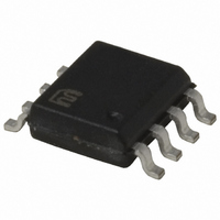
MIC4451YM TR Micrel Inc, MIC4451YM TR Datasheet - Page 11

MIC4451YM TR
Manufacturer Part Number
MIC4451YM TR
Description
IC DRIVER MOSFET 12A HS 8-SOIC
Manufacturer
Micrel Inc
Specifications of MIC4451YM TR
Configuration
Low-Side
Input Type
Inverting
Delay Time
15ns
Current - Peak
12A
Number Of Configurations
1
Number Of Outputs
1
Voltage - Supply
4.5 V ~ 18 V
Operating Temperature
-40°C ~ 85°C
Mounting Type
Surface Mount
Package / Case
8-SOIC (3.9mm Width)
Number Of Drivers
1
Driver Configuration
Inverting
Driver Type
Low Side
Input Logic Level
CMOS/TTL
Rise Time
40ns
Fall Time
50ns
Propagation Delay Time
60ns
Operating Supply Voltage (max)
18V
Peak Output Current
12mA
Power Dissipation
1.04W
Output Resistance
0.8Ohm
Operating Supply Voltage (min)
4.5V
Operating Temp Range
-40C to 85C
Operating Temperature Classification
Industrial
Mounting
Surface Mount
Pin Count
8
Lead Free Status / RoHS Status
Lead free / RoHS Compliant
High Side Voltage - Max (bootstrap)
-
Lead Free Status / Rohs Status
Compliant
Other names
MIC4451YMTR
MIC4451YMTR
MIC4451YMTR
Transition Power Dissipation
Transition power is dissipated in the driver each time its
output changes state, because during the transition, for
a very brief interval, both the N- and P-channel
MOSFETs
simultaneously, and a current is conducted through them
from V
approximately:
where (A × s) is a time-current factor derived from the
typical characteristic curve “Crossover Energy vs.
Supply Voltage.” Total power (P
described is:
Definitions
C
D = Duty Cycle expressed as the fraction of time the
input to the driver is high.
f = Operating Frequency of the driver in Hertz
I
inputs are high and neither output is loaded.
I
inputs are low and neither output is loaded.
I
P
P
load in Watts.
P
P
changes states (“shoot-through current”) in Watts.
NOTE: The “shoot-through” current from a dual
transition (once up, once down) for both drivers is
stated in Figure 7 in ampere-nanoseconds. This
figure must be multiplied by the number of
repetitions per second (frequency) to find Watts.
R
V
H
L
D
Micrel Inc.
January 2011
D
L
Q
T
S
L
O
= Power supply current drawn by a driver when both
= Output current from a driver in Amps.
= Power supply current drawn by a driver when both
= Load Capacitance in Farads.
= Power supply voltage to the IC in Volts.
= Total power dissipated in a driver in Watts.
= Power dissipated in the driver due to the driver’s
= Power dissipated in a quiescent driver in Watts.
= Output resistance of a driver in Ohms.
= Power dissipated in a driver when the output
S
P
P
to ground. The transition power dissipation is
T
D
= 2 f V
= P
in
L
+ P
S
the
(A × s)
Q
+ P
output
T
totem-pole
D
) then, as previously
are
ON
11
MIC4451/4452
M9999-011811


