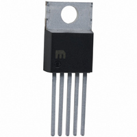
MIC4452ZT Micrel Inc, MIC4452ZT Datasheet - Page 10

MIC4452ZT
Manufacturer Part Number
MIC4452ZT
Description
IC DRIVR MOSF 12A LOSIDE TO220-5
Manufacturer
Micrel Inc
Datasheet
1.MIC4452YM_TR.pdf
(14 pages)
Specifications of MIC4452ZT
Configuration
Low-Side
Input Type
Non-Inverting
Delay Time
15ns
Current - Peak
12A
Number Of Configurations
1
Number Of Outputs
1
Voltage - Supply
4.5 V ~ 18 V
Operating Temperature
0°C ~ 70°C
Mounting Type
Through Hole
Package / Case
TO-220-5 (Straight Leads)
Number Of Drivers
1
Driver Configuration
Non-Inverting
Driver Type
Low Side
Input Logic Level
CMOS/TTL
Rise Time
40ns
Fall Time
50ns
Propagation Delay Time
60ns
Operating Supply Voltage (max)
18V
Peak Output Current
12mA
Power Dissipation
2W
Output Resistance
0.8Ohm
Operating Supply Voltage (min)
4.5V
Operating Temp Range
0C to 70C
Operating Temperature Classification
Commercial
Mounting
Through Hole
Pin Count
5 +Tab
Package Type
TO-220
Lead Free Status / RoHS Status
Lead free / RoHS Compliant
High Side Voltage - Max (bootstrap)
-
Lead Free Status / Rohs Status
Compliant
Other names
576-1212
Available stocks
Company
Part Number
Manufacturer
Quantity
Price
Company:
Part Number:
MIC4452ZT
Manufacturer:
FSC
Quantity:
7 000
Resistive Load Power Dissipation
Dissipation caused by a resistive load can be calculated
as:
where:
I = the current drawn by the load
R
is high, at the power supply voltage used. (See data
sheet)
D = fraction of time the load is conducting (duty cycle)
Capacitive Load Power Dissipation
Dissipation caused by a capacitive load is simply the
energy placed in, or removed from, the load capacitance
by the driver. The energy stored in a capacitor is
described by the equation:
As this energy is lost in the driver each time the load is
charged or discharged, for power dissipation calculations
the 1/2 is removed. This equation also shows that it is
good practice not to place more voltage on the capacitor
than is necessary, as dissipation increases as the
square of the voltage applied to the capacitor. For a
driver with a capacitive load:
where:
f = Operating Frequency
C = Load Capacitance
V
Micrel Inc.
January 2011
S
O
= Driver Supply Voltage
= the output resistance of the driver when the output
Table 1: MIC4451 Maximum Operating Frequency
P
E = 1/2 C V
P
L
L
= I
= f C (V
18V
15V
10V
VS
5V
2
R
O
D
S
2
)
2
Max. Frequency
220kHz
300kHz
640kHz
2MHz
10
Inductive Load Power Dissipation
For inductive loads the situation is more complicated.
For the part of the cycle in which the driver is actively
forcing current into the inductor, the situation is the same
as it is in the resistive case:
However, in this instance the R
the on resistance of the driver when its output is in the
high state, or its on resistance when the driver is in the
low state, depending on how the inductor is connected,
and this is still only half the story. For the part of the
cycle when the inductor is forcing current through the
driver, dissipation is best described as:
where V
driver (generally around 0.7V). The two parts of the load
dissipation must be summed in to produce P
Quiescent Power Dissipation
Quiescent power dissipation (P
input section) depends on whether the input is high or
low. A low input will result in a maximum current drain
(per driver) of ≤ 0.2mA; a logic high will result in a
current drain of ≤ 3.0mA. Quiescent power can therefore
be found from:
where:
I
I
D = fraction of time input is high (duty cycle)
V
H
L
S
= quiescent current with input low
= quiescent current with input high
= power supply voltage
P
P
P
P
D
L1
L2
L
Q
is the forward drop of the clamp diode in the
= P
= V
= I
= I V
2
L1
S
R
[D I
D
+ P
O
(1 – D)
D
H
L2
+ (1 – D) I
L
O
]
Q
required may be either
, as described in the
MIC4451/4452
M9999-011811
L
:


