IR4427 International Rectifier, IR4427 Datasheet - Page 2
IR4427
Manufacturer Part Number
IR4427
Description
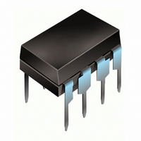
IC DRIVER DUAL LOW SIDE 8-DIP
Manufacturer
International Rectifier
Datasheet
1.IR4427PBF.pdf
(12 pages)
Specifications of IR4427
Configuration
Low-Side
Input Type
Non-Inverting
Delay Time
85ns
Current - Peak
2.3A
Number Of Configurations
2
Number Of Outputs
2
Voltage - Supply
6 V ~ 20 V
Operating Temperature
-40°C ~ 125°C
Mounting Type
Through Hole
Package / Case
8-DIP (0.300", 7.62mm)
Lead Free Status / RoHS Status
Contains lead / RoHS non-compliant
High Side Voltage - Max (bootstrap)
-
Other names
*IR4427
Available stocks
Company
Part Number
Manufacturer
Quantity
Price

Part Number:
IR4427
Manufacturer:
IOR
Quantity:
20 000
Company:
Part Number:
IR4427PBF
Manufacturer:
International Rectifier
Quantity:
1 985
Part Number:
IR4427PBF
Manufacturer:
IR
Quantity:
20 000
Part Number:
IR4427S
Manufacturer:
IR
Quantity:
20 000
Company:
Part Number:
IR4427STRPBF
Manufacturer:
IR
Quantity:
101
Part Number:
IR4427STRPBF
Manufacturer:
IR
Quantity:
20 000


IR4426/IR4427/IR4428(S) & (PbF)
Absolute Maximum Ratings
Absolute maximum ratings indicate sustained limits beyond which damage to the device may occur. All voltage param-
eters are absolute voltages referenced to GND. The thermal resistance and power dissipation ratings are measured
under board mounted and still air conditions.
2
DC Electrical Characteristics
V
applicable to input leads: INA and INB. The V
output leads: OUTA and OUTB.
Recommended Operating Conditions
The input/output logic timing diagram is shown in figure 1. For proper operation the device should be used within the
recommended conditions. All voltage parameters are absolute voltages referenced to GND.
Symbol
Symbol
Symbol
BIAS
Rth
V
V
V
V
V
P
T
V
V
T
T
T
IH
IN
(V
O
IN
S
D
S
L
O
A
J
S
JA
S
) = 15V, T
(IR4426)
Logic “0” input voltage (OUTA=LO),
input voltage (OUTB=HI) (IR4428)
Fixed supply voltage
Output voltage
Logic input voltage
Package power dissipation @ T
Thermal resistance, junction to ambient
Junction temperature
Storage temperature
Lead temperature (soldering, 10 seconds)
Fixed supply voltage
Output voltage
Logic input voltage
Ambient temperature
Logic “0” input voltage (OUTA=LO, OUTB=LO)
Logic “1” input voltage (OUTA=HI, OUTB=HI)
(IR4427)
Definition
Definition
A
= 25°C unless otherwise specified. The V
Definition
ADVANCE INFORMATION
O
and I
A
+25°C
O
Logic “1”
parameters are referenced to GND and are applicable to the
(8 Lead PDIP)
(8 lead SOIC)
(8 lead PDIP)
(8 lead SOIC)
IN
, and I
Min. Typ. Max. Units Test Conditions
2.7
IN
parameters are referenced to GND and are
—
Min.
Min.
-0.3
-0.3
-0.3
-55
-40
—
—
—
—
—
—
—
6
0
0
V
V
V
Max.
Max.
S
0.625
S
125
200
150
150
300
125
1.0
25
V
V
20
+ 0.3
+ 0.3
S
S
www.irf.com
Units
Units
°C/W
W
°C
V
°C
V
Related parts for IR4427
Image
Part Number
Description
Manufacturer
Datasheet
Request
R

Part Number:
Description:
SCHOTTKY RECTIFIER
Manufacturer:
International Rectifier Corp.
Datasheet:
Part Number:
Description:
SCHOTTKY RECTIFIER
Manufacturer:
International Rectifier Corp.
Datasheet:
Part Number:
Description:
SCHOTTKY RECTIFIER
Manufacturer:
International Rectifier Corp.
Datasheet:
Part Number:
Description:
SCHOTTKY RECTIFIER
Manufacturer:
International Rectifier Corp.
Datasheet:
Part Number:
Description:
SCHOTTKY RECTIFIER
Manufacturer:
International Rectifier Corp.
Datasheet:
Part Number:
Description:
SCHOTTKY RECTIFIER
Manufacturer:
International Rectifier Corp.
Datasheet:
Part Number:
Description:
SCHOTTKY RECTIFIER
Manufacturer:
International Rectifier Corp.
Datasheet:
Part Number:
Description:
SCHOTTKY RECTIFIER
Manufacturer:
International Rectifier Corp.
Datasheet:
Part Number:
Description:
SCHOTTKY RECTIFIER
Manufacturer:
International Rectifier Corp.
Datasheet:
Part Number:
Description:
SCHOTTKY RECTIFIER
Manufacturer:
International Rectifier Corp.
Datasheet:
Part Number:
Description:
SCHOTTKY RECTIFIER
Manufacturer:
International Rectifier Corp.
Datasheet:
Part Number:
Description:
SCHOTTKY RECTIFIER
Manufacturer:
International Rectifier Corp.
Datasheet:
Part Number:
Description:
SCHOTTKY RECTIFIER
Manufacturer:
International Rectifier Corp.
Datasheet:
Part Number:
Description:
SCHOTTKY RECTIFIER
Manufacturer:
International Rectifier Corp.
Datasheet:
Part Number:
Description:
SCHOTTKY RECTIFIER
Manufacturer:
International Rectifier Corp.
Datasheet: