MIC4452BM Micrel Inc, MIC4452BM Datasheet
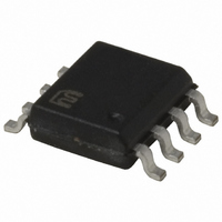
IC DRIVER MOSF 12A LO SIDE 8SOIC

MIC4452BM

Manufacturer Part Number
MIC4452BM
Description
IC DRIVER MOSF 12A LO SIDE 8SOIC
Manufacturer
Micrel Inc
Datasheets

Specifications of MIC4452BM

Rise Time
20ns
Mounting Type
Surface Mount
Configuration
Low-Side
Input Type
Non-Inverting
Delay Time
15ns
Current - Peak
12A
Number Of Configurations
1
Number Of Outputs
1
Voltage - Supply
4.5 V ~ 18 V
Operating Temperature
-40°C ~ 85°C
Package / Case
8-SOIC (3.9mm Width)
Device Type
MOSFET
Driver Case Style
SOIC
No. Of Pins
8
Peak Output High Current, Ioh
12A
Supply Voltage Min
4.5V
Peak Reflow Compatible (260 C)
No
Number Of Drivers
1
Driver Configuration
Non-Inverting
Driver Type
Low Side
Input Logic Level
CMOS/TTL
Fall Time
50ns
Propagation Delay Time
60ns
Operating Supply Voltage (max)
18V
Peak Output Current
12mA
Power Dissipation
1.04W
Output Resistance
0.8Ohm
Operating Supply Voltage (min)
4.5V
Turn Off Delay Time
80fs
Turn On Delay Time (max)
40ps
Operating Temp Range
-40C to 85C
Operating Temperature Classification
Industrial
Mounting
Surface Mount
Pin Count
8
Package Type
SOIC
Lead Free Status / RoHS Status
Contains lead / RoHS non-compliant
High Side Voltage - Max (bootstrap)
-
Lead Free Status / RoHS Status
Not Compliant, Contains lead / RoHS non-compliant
MIC4451/4452
General Description
MIC4451 and MIC4452 CMOS MOSFET drivers are tough,
efficient, and easy to use. The MIC4451 is an inverting driver,
while the MIC4452 is a non-inverting driver.
Both versions are capable of 12A (peak) output and can drive
the largest MOSFETs with an improved safe operating mar-
gin. The MIC4451/4452 accepts any logic input from 2.4V to
V
Proprietary circuits allow the input to swing negative by as
much as 5V without damaging the part. Additional circuits
protect against damage from electrostatic discharge.
MIC4451/4452 drivers can replace three or more discrete
components, reducing PCB area requirements, simplifying
product design, and reducing assembly cost.
Modern Bipolar/CMOS/DMOS construction guarantees
freedom from latch-up. The rail-to-rail swing capability of
CMOS/DMOS insures adequate gate voltage to the MOS-
FET during power up/down sequencing. Since these devices
are fabricated on a self-aligned process, they have very low
crossover current, run cool, use little power, and are easy
to drive.
Functional Diagram
July 2005
S
without external speed-up capacitors or resistor networks.
Micrel, Inc. • 2180 Fortune Drive • San Jose, CA 95131 • USA • tel + 1 (408) 944-0800 • fax + 1 (408) 474-1000 • http://www.micrel.com
IN
2kΩ
0.1mA
0.3mA
NONINVERTING
1
I N V E R T I N G
MIC4451
MIC4452
Features
• BiCMOS/DMOS Construction
• Latch-Up Proof: Fully Isolated Process is Inherently
• Input Will Withstand Negative Swing of Up to 5V
• Matched Rise and Fall Times ............................... 25ns
• High Peak Output Current .............................12A Peak
• Wide Operating Range .............................. 4.5V to 18V
• High Capacitive Load Drive ........................... 62,000pF
• Low Delay Time .............................................30ns Typ.
• Logic High Input for Any Voltage from 2.4V to V
• Low Supply Current .............. 450µA With Logic 1 Input
• Low Output Impedance .........................................1.0Ω
• Output Voltage Swing to Within 25mV of GND or V
• Low Equivalent Input Capacitance (typ) ................. 7pF
Applications
• Switch Mode Power Supplies
• Motor Controls
• Pulse Transformer Driver
• Class-D Switching Amplifiers
• Line Drivers
• Driving MOSFET or IGBT Parallel Chip Modules
• Local Power ON/OFF Switch
• Pulse Generators
Immune to Any Latch-up.
12A-Peak Low-Side MOSFET Driver
Bipolar/CMOS/DMOS Process
MIC4451/4452
GND
V
S
OUT
MIC4451/4452
Micrel, Inc.
S
S

Related parts for MIC4452BM

MIC4452BM Summary of contents

Page 1

MIC4451/4452 General Description MIC4451 and MIC4452 CMOS MOSFET drivers are tough, efficient, and easy to use. The MIC4451 is an inverting driver, while the MIC4452 is a non-inverting driver. Both versions are capable of 12A (peak) output and can drive ...

Page 2

... MIC4451/4452 Ordering Information Part Number Standard Pb-Free MIC4451BN MIC4451YN MIC4451BM MIC4451YM MIC4451CT MIC4451ZT MIC4452BN MIC4452YN MIC4452BM MIC4452YM MIC4452CT MIC4452ZT Pin Configurations Pin Description Pin Number Pin Number Pin Name TO-220-5 DIP, SOIC TAB MIC4451/4452 Temperature Range Package –40ºC to +85ºC 8-pin Plastic DIP – ...

Page 3

MIC4451/4452 Absolute Maximum Ratings Supply Voltage .............................................................. 20V Input Voltage ...................................V Input Current (V > .............................................. Power Dissipation, T ≤ 25°C AMBIENT PDIP .................................................................... 960mW SOIC .................................................................. 1040mW 5-Pin TO-220 .............................................................. 2W Power Dissipation, ...

Page 4

MIC4451/4452 Electrical Characteristics: (Over operating temperature range with 4.5V < V Symbol Parameter INPUT V Logic 1 Input Voltage IH V Logic 0 Input Voltage IL V Input Voltage Range IN I Input Current IN OUTPUT V High Output Voltage ...

Page 5

MIC4451/4452 Typical Characteristic Curves Rise Time vs. Supply Voltage 220 200 180 160 140 47,000pF 120 100 80 22,000pF 60 40 10,000pF SUPPLY VOLTAGE (V) Rise Time vs. Capacitive Load ...

Page 6

MIC4451/4452 Typical Characteristic Curves (Cont.) Propagation Delay vs. Supply Voltage SUPPLY VOLTAGE (V) Quiescent Supply Current vs. Temperature 1000 V = 18V ...

Page 7

MIC4451/4452 Applications Information Supply Bypassing Charging and discharging large capacitive loads quickly requires large currents. For example, changing a 10,000pF load to 18V in 50ns requires 3.6A. The MIC4451/4452 has double bonding on the supply pins, the ground pins and ...

Page 8

MIC4451/4452 Input Stage The input voltage level of the MIC4451 changes the quiescent supply current. The N channel MOSFET input stage transistor drives a 320µA current source load. With a logic “1” input, the maximum quiescent supply current is 400µA. ...

Page 9

MIC4451/4452 As this energy is lost in the driver each time the load is charged or discharged, for power dissipation calculations the 1/2 is removed. This equation also shows that it is good practice not to place more voltage on ...

Page 10

MIC4451/4452 0 V MIC4451/4452 +18 V WIMA MK22 1 µF 5.0V 1 TEK CURRENT PROBE 6302 MIC4452 5 0.1µF 0.1µF 4 Figure 6. Peak Output Current Test Circuit 10 Micrel, Inc 15,000 ...

Page 11

MIC4451/4452 Package Information 0.018 (0.57) 0.026 (0.65) 0.157 (3.99) 0.150 (3.81) 0.064 (1.63) 0.045 (1.14) July 2005 PIN 1 DIMENSIONS: INCH (MM) 0.380 (9.65) 0.370 (9.40) 0.135 (3.43) 0.125 (3.18) 0.380 (9.65) 0.130 (3.30) 0.320 (8.13) 0.100 (2.54) 0.0375 (0.952) ...

Page 12

... REF (6.81 REF) MICREL INC. 2180 FORTUNE DRIVE SAN JOSE, CA 95131 USA + 1 (408) 944-0800 TEL This information furnished by Micrel in this data sheet is believed to be accurate and reliable. However no responsibility is assumed by Micrel for its use. Micrel reserves the right to change circuitry and specifications at any time without notification to the customer. ...

Related keywords