VO3150A-X007T Vishay, VO3150A-X007T Datasheet
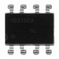
IC DRIVER IGBT/MOSFET 0.5A 8-SMD

VO3150A-X007T

Manufacturer Part Number
VO3150A-X007T
Description
IC DRIVER IGBT/MOSFET 0.5A 8-SMD
Manufacturer
Vishay
Type
High Side/Low Side Driverr
Datasheet

Specifications of VO3150A-X007T

Isolation Voltage
5300 Vrms
Input Type
Non-Inverting
Number Of Outputs
1
Current - Output / Channel
500mA
Current - Peak Output
500mA
Voltage - Supply
15 V ~ 32 V
Operating Temperature
-40°C ~ 110°C
Mounting Type
Surface Mount
Package / Case
8-SMD (300 mil)
Fall Time
0.1 us
Logic Gate Type
IGBT
Rise Time
0.1 us
Configuration
1 Channel
Output Type
Integrated Photo IC
Maximum Propagation Delay Time
0.4 us
Maximum Forward Diode Voltage
1.6 V
Minimum Forward Diode Voltage
1 V
Maximum Reverse Diode Voltage
5 V
Maximum Forward Diode Current
25 mA
Maximum Continuous Output Current
0.5 A
Maximum Power Dissipation
295 mW
Maximum Operating Temperature
+ 110 C
Minimum Operating Temperature
- 40 C
No. Of Channels
1
Optocoupler Output Type
Gate Drive
Input Current
16mA
Output Voltage
500mV
Opto Case Style
SMD
No. Of Pins
8
Output Current
0.5A
Number Of Elements
1
Forward Voltage
1.6V
Forward Current
25mA
Package Type
PDIP SMD
Power Dissipation
295mW
Propagation Delay Time
400ns
Pin Count
8
Mounting
Surface Mount
Reverse Breakdown Voltage
5V
Operating Temperature Classification
Industrial
Lead Free Status / RoHS Status
Lead free / RoHS Compliant
On-state Resistance
-
Lead Free Status / Rohs Status
Compliant
Other names
751-1476-2

Available stocks

Company
Part Number
Manufacturer
Quantity
Price
Company:
Part Number:
VO3150A-X007T
Quantity:
70 000
DESCRIPTION
The VO3150A consists of a LED optically coupled to an
integrated circuit with a power output stage. This
optocoupler is ideally suited for driving power IGBTs and
MOSFETs used in motor control inverter applications. The
high operating voltage range of the output stage provides
the drive voltages required by gate controlled devices. The
voltage and current supplied by this optocoupler makes it
ideally suited for directly driving IGBTs with ratings up to 800
V/20 A. For IGBTs with higher ratings, the VO3150A can be
used to drive a discrete power stage which drives the IGBT
gate.
Document Number: 81808
Rev. 1.1, 14-Jan-10
19813
ORDERING INFORMATION
PACKAGE
DIP-8
SMD-8, option 7
TRUTH TABLE
LED
Off
On
On
On
V
O
0.5 A Output Current IGBT and MOSFET Driver
PART NUMBER
3
20530_1
1
NC
NC
C
A
1
2
3
4
For technical questions, contact:
5
Shield
“POSITIVE GOING”
11 V to 13.5 V
13.5 V to 32 V
0
(TURN ON)
0 V to 32 V
0 V to 11 V
V
CC
- V
A
EE
D E
V
8
7
6
5
V
V
V
V
VO3150A-X007T
CC
O
O
EE
-
VO3150A
UL, cUL
optocoupleranswers@vishay.com
X
FEATURES
• 0.5 A minimum peak output current
• 25 kV/μs minimum common mode rejection
• I
• Under
• Wide operating V
• 0.4 μs maximum propagation delay
• Industrial temperature range: - 40 °C to 110 °C
• 0.5 V maximum low level output voltage (V
• Compliant to RoHS directive 2002/95/EC
APPLICATIONS
• Isolated IGBT/MOSFET gate driver
• AC and brushless DC motor drives
• Induction stove top
• Industrial inverters
• Switch mode power supplies (SMPS)
• Uninterruptible power supplies (UPS)
AGENCY APPROVALS
• UL - file no. E52744 system code H, double protection
• cUL - file no. E52744, equivalent to CSA bulletin 5A
• DIN EN 60747-5-5 (VDE0884) available with option 1
PACKAGE OPTION
(CMR) at V
hysteresis
CC
“NEGATIVE GOING”
0
= 2.5 mA maximum supply current
(TURN OFF)
9.5 V to 12 V
12 V to 32 V
0 V to 9.5 V
0 V to 32 V
V
CC
voltage
- V
CM
0
EE
= 1500 V
CC
7
lock-out
range: 15 V to 32 V
Vishay Semiconductors
TAPE AND
REEL
T
VO3150A-X017T
UL, cUL, VDE
(UVLO)
7.62 mm
-
DIP-8
Transition
High
Low
Low
VO3150A
V
with
O
OL
www.vishay.com
> 0.7 mm
)
Option 7
1

Related parts for VO3150A-X007T

VO3150A-X007T Summary of contents

Page 1

... Uninterruptible power supplies (UPS) AGENCY APPROVALS • file no. E52744 system code H, double protection • cUL - file no. E52744, equivalent to CSA bulletin 5A • DIN EN 60747-5-5 (VDE0884) available with option PACKAGE OPTION UL, cUL VO3150A VO3150A-X007T “POSITIVE GOING” “NEGATIVE GOING” (TURN ON) (TURN OFF ...

Page 2

... VO3150A Vishay Semiconductors ABSOLUTE MAXIMUM RATINGS PARAMETER INPUT Input forward current Peak transient input current Reverse input voltage Output power dissipation OUTPUT (2) High peak output current (2) Low peak output current Supply voltage Output voltage Output power dissipation OPTOCOUPLER Isolation test voltage (between emitter and detector, climate per DIN 500414, part 2, Nov ...

Page 3

... μA BVΡ MHz ≥ UVLO UVLO- UVLO HYS = ground) unless otherwise specified. Typical values are characteristics of the device and are optocoupleranswers@vishay.com VO3150A Vishay Semiconductors T A θ CA Package T C θ θ θ θ θ BA 19996 T A MIN. TYP. MAX. 0.5 0.5 ...

Page 4

... VO3150A Vishay Semiconductors TEST CIRCUITS 8 1 0.1 µ 20973_1 Fig Test Circuit 0.1 µ 20975_1 Fig Test Circuit 0.1 µ 20977_1 Fig Test Circuit OH SWITCHING CHARACTERISTICS PARAMETER Propagation delay time to logic R g (1) low output Propagation delay time to logic R g (1) high output ...

Page 5

... UVLO turn off delay Notes (1) This load condition approximates the gate load of a 1200 V/25 A IGBT. (2) Pulse width distortion (PWD) is defined as |t (3) The difference between t and t between any two VO3150A parts under the same test condition. PHL PLH 500 Ω kHz ...

Page 6

... VO3150A Vishay Semiconductors SAFETY AND INSULATION RATINGS PARAMETER Climatic classification (according to IEC 68 part 1) Comparative tracking index V IOTM V IORM Creepage distance Clearance distance Creepage distance Clearance distance Note • As per IEC 60747-5-5, §7.4.3.8.1, this optocoupler is suitable for “safe electrical insulation” only within the safety ratings. Compliance with the safety ratings shall be ensured by means of prodective circuits ...

Page 7

... Rev. 1.1, 14-Jan-10 0.5 A Output Current IGBT and MOSFET Driver 25 ° °C 0.6 0.8 21711 - 40 °C 110 °C 0.6 0.8 21712-1 Fig Low to High Current Threshold vs. Temperature 80 100 120 21752 optocoupleranswers@vishay.com VO3150A Vishay Semiconductors 2 for I F CCH for I F CCL 2 ° ...

Page 8

... VO3150A Vishay Semiconductors 500 mA ° Ω Duty cycle = 50 % 400 kHz 300 t PHL 200 t PLH 100 Supply Voltage (V) 21736 CC Fig Propagation Delay vs. Supply Voltage 500 Ω, C 400 Duty cycle = kHz 300 200 100 Temperature (°C) 21737 A Fig Propagation Delay vs. Temperature 500 mA °C ...

Page 9

... Option 7 7.62 typ. 0.7 4.6 4.1 8 min. 8.4 min. 18450-4 10.3 max. VO3150A V YWW H 68 21764-43 optocoupleranswers@vishay.com VO3150A Vishay Semiconductors ISO method A 7.62 typ. 5.84 10° 6.35 2.79 3.30 3° to 9° 0.2 0.3 www.vishay.com 9 ...

Page 10

... Vishay product could result in personal injury or death. Customers using or selling Vishay products not expressly indicated for use in such applications their own risk and agree to fully indemnify and hold Vishay and its distributors harmless from and against any and all claims, liabilities, expenses and damages arising or resulting in connection with such use or sale, including attorneys fees, even if such claim alleges that Vishay or its distributor was negligent regarding the design or manufacture of the part ...

Related keywords