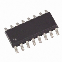
U6820BM-MFPG3Y Atmel, U6820BM-MFPG3Y Datasheet

U6820BM-MFPG3Y
Specifications of U6820BM-MFPG3Y
Available stocks
Related parts for U6820BM-MFPG3Y
U6820BM-MFPG3Y Summary of contents
Page 1
... Its partitioning into 4 high-side and 4 low-side driver stages allows an easy connection of either 4 half- bridges or 2 H-bridges on the pc board. The U6820BM communicates with a micro- controller via an 8-bit serial interface. Integrated protection against short circuit and overtemperature give added value. EMI protection and 2-kV ESD protection together with automotive qualification referring to conducted interference (ISO/TR 7637/1) make this IC ideal for both automotive and industrial applications ...
Page 2
... Clock line for 8-bit control shift register 13 DI Data line for 8-bit control shift register 14 STATUS Status output (H = fault, diagnostic “H” if all driver stages are switched off) 15 LS4 Output low side 4 16 HS4 Output high side 4 U6820BM HS1 2 15 LS1 ...
Page 3
... The detection of overtemperature is latched internally reset by the falling edge of the 4 clock (bit data transfer if overtemperature is no longer present. 4527B–BCD–09/ clock. The reset is initiated by the falling edge of the 2 U6820BM control bit. The priority protects the IC against th clock (bit 7) of the next data nd clock (bit 1) of the next ...
Page 4
... All output stages are protected against electrostatic discharge (HBM) with external components (see Table 4-1. Timing of the STATUS Output Shift Register Command Register U6820BM 4 = 3.7V. The outputs are activated after the first data CC Figure 8-1), all other pins are protected (HBM). Low-side Switch Condition LS1 LS2 LS3 All out = OK off off ...
Page 5
... V CLKL CC t 1/2 V CLKCS CC t 1/2 V CSCLK CC t 1/2 V DICLK CC t 1/2 V DIH 1/2 V CLKCSH 4527B–BCD–09/05 CLKH 10% on CLK, DI and CLK, DI and 50% MSB Minimum Maximum 250 100 100 150 100 80 100 100 250 U6820BM 50 50% t CLKCSH Unit ...
Page 6
... Figure 4-2. Block Diagram of the Control Interface 8CLK CLK CLK DIN DIN Load P-ON-Reset Th-protection All norm = 0 U6820BM 6 Serial-Parallel Interface Counter Shift register DIN DIN DIN DIN DIN Command register DFF DFF POR norm LSB Q1 Q0 DIN DIN DFF DFF DFF ...
Page 7
... I and I 1H-4H 1L- stg Symbol R thJA R thJC Pin Symbol VCC 11, 12, 13 CS, CLK, DI 11, 12, 13 CS, CLK STATUS f CLK T j U6820BM Minimum Maximum –0.3 +40 –0.3 +7 –0 0.5 VCC –0 0.3 VCC 0 –40 +150 –55 +150 Value 110 26 Value 4.5 to 5.5 –0 VCC (0 ...
Page 8
... Pull-down current 5 Serial Interface – Output: STATUS 5.1 Output voltage low level 5.2 Output voltage high level *) Type means: A =100% tested 100% correlation tested Characterized on samples Design parameter U6820BM 8 < 150°C; unless otherwise specified j Test Conditions Pin Symbol No external load ...
Page 9
... Thermal protection V CC Power-on reset Current Current limiter limiter LS2 LS1 4.7nF 4.7nF 27k 27k ca. 4 Ohm (I Lim for inv. supply) and V as close as possible to the power supply and GND µF electrolytic in parallel with CC U6820BM V BATT 100nF 47µF GND S 9 ...
Page 10
... Ordering Information Extended Type Number U6820BM-MFPG3Y 10. Package Information Package SO16 Dimensions 11. Revision History Please note that the following page numbers referred to in this section refer to the specific revision mentioned, not to this document. Revision No. 4527B-BCD-09/05 U6820BM 10 Package SO16 10.0 9.85 0.4 1.27 8 ...
Page 11
... Disclaimer: The information in this document is provided in connection with Atmel products. No license, express or implied, by estoppel or otherwise, to any intellectual property right is granted by this document or in connection with the sale of Atmel products. EXCEPT AS SET FORTH IN ATMEL’S TERMS AND CONDI- TIONS OF SALE LOCATED ON ATMEL’S WEB SITE, ATMEL ASSUMES NO LIABILITY WHATSOEVER AND DISCLAIMS ANY EXPRESS, IMPLIED OR STATUTORY WARRANTY RELATING TO ITS PRODUCTS INCLUDING, BUT NOT LIMITED TO, THE IMPLIED WARRANTY OF MERCHANTABILITY, FITNESS FOR A PARTICULAR PURPOSE, OR NON-INFRINGEMENT ...


