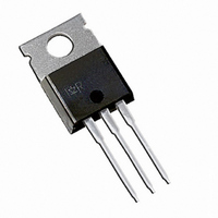
IPS0151 International Rectifier, IPS0151 Datasheet - Page 3

IPS0151
Manufacturer Part Number
IPS0151
Description
IC MOSFET PWR SWITCH TO-220AB
Manufacturer
International Rectifier
Type
Low Sider
Datasheet
1.IPS0151.pdf
(13 pages)
Specifications of IPS0151
Input Type
Non-Inverting
Number Of Outputs
1
On-state Resistance
20 mOhm
Current - Output / Channel
4.3A
Current - Peak Output
45A
Voltage - Supply
4 V ~ 6 V
Operating Temperature
-40°C ~ 150°C
Mounting Type
Through Hole
Package / Case
TO-220-3 (Straight Leads)
Lead Free Status / RoHS Status
Contains lead / RoHS non-compliant
Other names
*IPS0151
Q827406
Q827406
Available stocks
Company
Part Number
Manufacturer
Quantity
Price
Company:
Part Number:
IPS0151
Manufacturer:
IR
Quantity:
12 500
Company:
Part Number:
IPS0151S
Manufacturer:
IR
Quantity:
5 510
Company:
Part Number:
IPS0151S
Manufacturer:
XILINK
Quantity:
5 510
Static Electrical Characteristics
(T j = 25
Switching Electrical Characteristics
V cc = 14V, Resistive Load = 3 , Rinput = 50
Symbol Parameter
Protection Characteristics
www.irf.com
T on
T r
T rf
T off
T f
Q in
Symbol Parameter
T sd
I sd
V
T reset
EOI_OT
Symbol Parameter
R ds(on)
I dss1
@Tj=25
I dss2
@Tj=25
V
V
V in
V in
I in , -on
I in, -off
reset
clamp 1
clamp 2
clamp
th
o
o
o
C unless otherwise specified.)
C
C
Turn-on delay time
Rise time
Time to (final R ds(on) 1.3%)
Turn-off delay time
Fall time
Total gate charge
Over temperature threshold
Over current threshold
IN protection reset threshold
Time to reset protection
Short circuit energy (see application note)
ON state resistance T j = 25
Drain to source leakage current
Drain to source leakage current
Drain to source clamp voltage 1
Drain to source clamp voltage 2
IN to source clamp voltage
IN threshold voltage
ON state IN positive current
OFF state IN positive current
T j = 150
o
C
o
C
100 u s pulse, T
Min.
Min.
Min.
0.05
0.8
0.4
1.5
20
10
47
50
25
50
—
—
—
—
—
0.2
2
0
0
7
1
j
= 25
Typ.
Typ. Max. Units Test Conditions
Typ.
0.25
165
400
130
o
0.9
3.8
1.5
1.1
2.3
0.5
8.1
1.6
30
35
10
20
35
52
55
90
C, (unless otherwise specified).
5
Max. Units Test Conditions
Max. Units Test Conditions
200
250
0.6
1.5
9.5
25
50
—
—
—
50
—
25
45
56
60
40
2
2
2
3
m
nC
o
A
V
V
C
A
A
J
s
s
See figure 2
V in = 5V
See fig. 1
See fig. 1
Vcc = 14V
V cc = 14V, T j = 25
V cc = 40V, T j = 25
I d = 20mA
I d =I shutdown
I in = 1 mA
I d = 50mA, V ds = 14V
V in = 5V
V in = 5V
over-current triggered
See figure 2
V in = 0V, Tj = 25
V in = 5V, I ds = 1A
IPS0151(S)
(see Fig.3 & 4)
(see Fig.3 & 4)
o
C
o
o
C
C
3


